Ultrahigh-pressure long-life throttle valve for testing high-pressure pump for petroleum drilling

An oil drilling and ultra-high pressure technology is applied in the field of ultra-high pressure and long-life throttle valves for oil drilling high-pressure pump testing. , The effect of reducing maintenance costs and prolonging service life

Pending Publication Date: 2022-07-01
中石化四机石油机械有限公司 +1
View PDF0 Cites 0 Cited by
  • Summary
  • Abstract
  • Description
  • Claims
  • Application Information

AI Technical Summary

Problems solved by technology

[0002] High-pressure pumps used in oil drilling and development need to be tested under pressure during the production process. During the test process, ultra-high pressure throttle valves are used as fluid control equipment to control the output pressure and flow of high-pressure pumps; Increase, the output pressure of the high-pressure pump used in existing oil drilling and development has reached 140MPa. When the high-pressure throttle valve is used alone under such a high fluid pressure, the speed of fluid flowing through the high-pressure throttle valve is extremely high, so the high-pressure throttle The erosion problem of the valve is extremely serious, resulting in a very short service life of the high-pressure throttle valve and its outlet connecting pipeline, which needs to be replaced after only 2-3 months of use, and the high-pressure throttle valve is expensive, so it is extremely It affects the testing cost of high-pressure pumps for drilling and mining in oilfields; in addition, the spool structure of existing high-pressure throttle valves mostly adopts single-end guide support, which is prone to fluid shock and vibration under ultra-high pressure conditions, causing the equipment to fail to work normally; The vibration of the high-pressure throttle valve will cause the valve core to break, and the broken valve core will instantly block the throttle channel, causing huge impact damage to the high-pressure pump and test equipment, which will easily lead to safety accidents
[0003] In order to solve the above problems, in the process of oil field drilling and production high-pressure pump testing, there is a way of using several high-pressure throttle valves to work in series at the same time, and through several high-pressure throttle valves connected in series to share the independent burden of a single high-pressure throttle valve in the past. Throttling pressure, thereby reducing the fluid velocity passing through the throttle valve, prolonging the service life of the high-pressure throttle valve and reducing the vibration during work; but this method also has some problems: 1. The cost of several high-pressure throttle valves working in series 2. When adjusting fluid pressure and flow, several high-pressure throttle valves need to be adjusted synchronously, but the working characteristics of each high-pressure throttle valve are inconsistent, so the actual adjustment and control are extremely difficult, resulting in the high-pressure pump working The characteristic test results are inaccurate; 3. Due to the large number of high-pressure throttle valves used, the overall working reliability is poor, and equipment accidents are prone to occur; 4. Several high-pressure throttle valves connected in series still have the risk of spool fracture

Method used


Image

  • Ultrahigh-pressure long-life throttle valve for testing high-pressure pump for petroleum drilling
  • Ultrahigh-pressure long-life throttle valve for testing high-pressure pump for petroleum drilling
  • Ultrahigh-pressure long-life throttle valve for testing high-pressure pump for petroleum drilling

Examples


Embodiment Construction

[0032] The present invention can be explained in detail through the following examples, and the purpose of disclosing the present invention is to protect all technical improvements within the scope of the present invention.

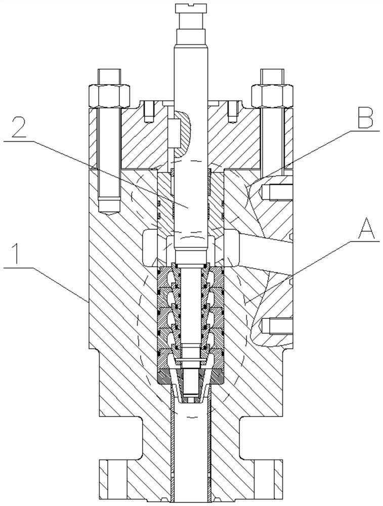
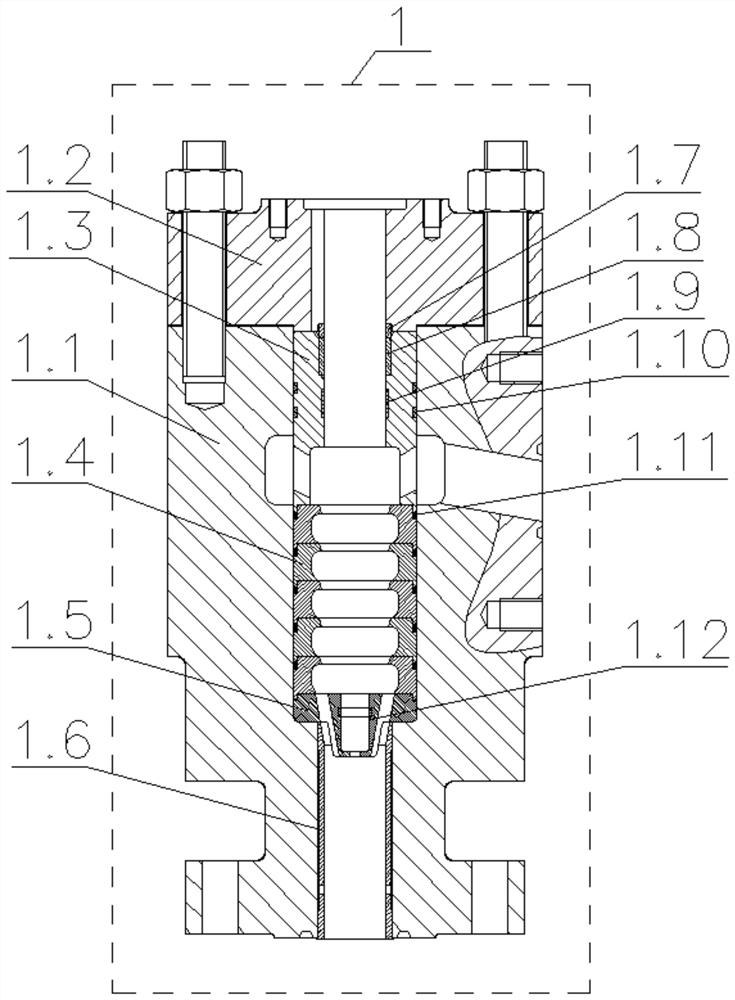
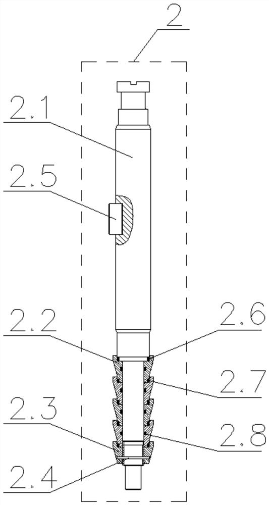
[0033] An ultra-high pressure long-life throttle valve for oil drilling high-pressure pump testing, comprising a valve body assembly 1 and a valve core assembly 2; the valve body assembly 1 includes a valve body 1.1, a valve cover 1.2, an upper valve sleeve 1.3, a valve seat 1.4, an outlet Valve seat 1.5; valve body 1.1 is provided with upper valve sleeve hole 1.1.1, valve body cavity 1.1.2, valve seat hole 1.1.4, valve body outlet hole 1.1.5, valve body cavity 1.1. 2 The side wall is provided with an inclined water inlet 1.1.3; the valve cover 1.2 is fixed on the upper end of the valve body 1.1; the upper valve sleeve 1.3 is fixed in the upper valve sleeve hole 1.1.1, the upper end of the upper valve sleeve 1.3 and the valve cover 1.2 The lower end is in...


PUM


Abstract

An ultrahigh-pressure long-service-life throttling valve for testing a high-pressure pump in petroleum drilling comprises a valve body assembly and a valve element assembly, and the valve element assembly is arranged in the valve body assembly in a sliding mode. A plurality of valve seats are fixedly arranged in the valve body assembly in an up-and-down overlapping mode, a plurality of valve elements are fixedly arranged in the valve element assembly in an up-and-down overlapping mode, and the valve seats are matched with the valve elements to form gap throttling conical rings and backflow cavities which are arranged in a multi-stage series connection mode. When ultrahigh-pressure fluid flows through the ultrahigh-pressure throttling valve, the pressure borne by each stage of gap throttling cone ring and the backflow cavity is greatly reduced through throttling of the gap throttling cone rings and the backflow cavity which are connected in series in multiple stages, and the erosion problem of the throttling valve is greatly solved; due to the design of supporting and guiding of the two ends of the valve element assembly, the anti-vibration performance of the throttling valve is greatly improved; the design of the minimum safe throttling gap is adopted between the valve element and the valve seat, even if the valve element is broken, the minimum throttling gap is still kept between the valve element and the valve seat, a throttling channel cannot be blocked, and therefore impact damage to a high-pressure pump and testing equipment cannot be generated.

Description

technical field [0001] The invention relates to the technical field of ultra-high pressure valves for testing high-pressure pumps in oil drilling and exploitation, in particular to an ultra-high-pressure and long-life throttle valve for testing high-pressure pumps in oil drilling. Background technique [0002] During the production process, the high-pressure pump used in oil drilling and development needs to be tested under pressure. During the test, an ultra-high pressure throttle valve is used as a fluid control device to control the pressure and flow output of the high-pressure pump. In addition, the output pressure of the high-pressure pump used in existing oil drilling and development has reached as high as 140MPa. When the high-pressure throttle valve is used alone under such a high fluid pressure, the speed of the fluid flowing through the high-pressure throttle valve is extremely high. The valve erosion problem is extremely serious, resulting in a very short service ...

Claims


Application Information

Patent Timeline
IPC IPC(8): F16K1/00F16K1/38F16K1/34F16K1/44F16K47/04F16K27/02F16K27/08F16K41/02
CPCF16K1/00F16K1/38F16K1/34F16K1/443F16K47/04F16K27/0254F16K27/08F16K41/02
Inventor 尹婷胡顺伍闻宇孔丽丽陈纪安樊鹏
Owner 中石化四机石油机械有限公司
Why Eureka
Try Eureka