
Heat dissipation control valve and heat dissipation system

A technology for controlling valves and valve bodies, which is applied in control valves, pump controls, multi-way valves, etc., and can solve problems such as dust accumulation

Pending Publication Date: 2022-06-24
ZHEJIANG HAIHONG HYDRAULIC TECH
View PDF0 Cites 0 Cited by
  • Summary
  • Abstract
  • Description
  • Claims
  • Application Information

AI Technical Summary

Problems solved by technology

[0003] Based on this, it is necessary to provide a heat dissipation control valve and a heat dissipation system to solve the problem that the blades of the fan and even other parts of the heat dissipation system will accumulate a large amount of dust when the fan works for a long time

Method used


Image

  • Heat dissipation control valve and heat dissipation system
  • Heat dissipation control valve and heat dissipation system
  • Heat dissipation control valve and heat dissipation system

Examples


Embodiment Construction

[0022] In the description of this application, it should be understood that the terms "center", "longitudinal", "lateral", "length", "width", "thickness", "upper", "lower", "front", " Back, Left, Right, Vertical, Horizontal, Top, Bottom, Inner, Outer, Clockwise, Counterclockwise, Axial , "radial", "circumferential" and other indicated orientations or positional relationships are based on the orientations or positional relationships shown in the accompanying drawings, and are only for the convenience of describing the application and simplifying the description, rather than indicating or implying the indicated device or Elements must have a particular orientation, be constructed and operate in a particular orientation, and therefore are not to be construed as limitations of the present application.

[0023] In addition, the terms "first" and "second" are only used for descriptive purposes, and should not be construed as indicating or implying relative importance or implying the...


PUM


Abstract

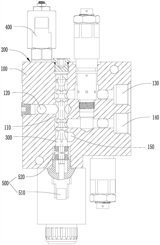
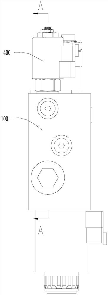
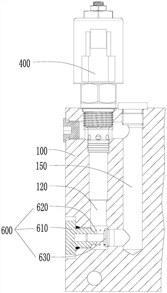
The invention relates to a heat dissipation control valve and a heat dissipation system, the heat dissipation control valve comprises a valve body and a valve rod, the valve body is provided with a valve cavity, a main oil inlet channel, a first working channel, a second working channel and an oil return channel, and the valve rod is movably arranged in the valve cavity to control the main oil inlet channel to communicate with the first working channel or the second working channel through the valve cavity. When the main oil inlet channel communicates with the first working channel, the heat dissipation control valve can drive the hydraulic motor to drive the fan to rotate clockwise, and when the main oil inlet channel communicates with the second working channel, the heat dissipation control valve can drive the hydraulic motor to drive the fan to rotate anticlockwise. The valve body is further provided with an overflow channel capable of being communicated with the main oil inlet channel and the oil return channel, the heat dissipation control valve further comprises an overflow valve, and the overflow valve is arranged on the overflow channel to control on-off of the overflow channel. According to the heat dissipation control valve and the heat dissipation system, the problem that a large amount of dust is accumulated on blades of the fan and even other parts of the heat dissipation system due to long-time working of the fan is solved.

Description

technical field [0001] The application relates to the technical field of construction machinery, and in particular, to a heat dissipation control valve and a heat dissipation system. Background technique [0002] Usually, construction machinery and equipment will generate a lot of heat during the working process. Therefore, it is necessary to use a heat dissipation system to dissipate heat from construction machinery and equipment. The heat dissipation system includes a fan, a hydraulic motor and a heat dissipation control valve. The fan is installed on the output shaft of the hydraulic motor. The heat dissipation control valve is connected to the hydraulic motor for driving the hydraulic motor to rotate. However, long-term operation of the fan will cause a large amount of dust to accumulate on the blades of the fan and even other parts of the cooling system, which in turn causes the cooling effect of the cooling control valve and the cooling system to deteriorate. SUMMARY...

Claims


Application Information

Patent Timeline
IPC IPC(8): F16K11/07F16K11/10F16K27/04F16K31/06F16K15/06F15B13/04F04D27/00F04D25/04F04D25/08F03C1/00
CPCF16K11/07F16K11/10F16K27/041F16K27/048F16K31/0613F16K31/0675F16K15/063F15B13/0402F15B13/027F04D27/00F04D25/04F04D25/08F03C1/003F03C1/001F15B2013/041F15B2013/002
Inventor 王新慧高利胡新科文小凤
Owner ZHEJIANG HAIHONG HYDRAULIC TECH
Learn More