
Extreme-high-temperature thermal intensity experiment system of complex curved surface structure for aerospace plane test

A technology for aerospace aircraft and complex curved surfaces, which is applied in the field of extreme high-temperature thermal strength experiment systems for complex curved surface structures used in aerospace aircraft testing. The effect of fast change speed and high temperature peak

Active Publication Date: 2022-06-17
CHINA AIRPLANT STRENGTH RES INST
View PDF7 Cites 9 Cited by
  • Summary
  • Abstract
  • Description
  • Claims
  • Application Information

AI Technical Summary

Problems solved by technology

[0002] When an aerospace aircraft flies at hypersonic speed in the atmosphere, its structural surface is subjected to severe aerodynamic heating. The aerodynamic heating temperature peak is high, the temperature change rate is large, and the thermal field is extremely complex. and evaluation are extremely challenging; in the face of complex curved surface temperature and thermal flow field distributions with local temperatures exceeding 1800°C and temperature changes exceeding 200°C / s, it is difficult for existing traditional experimental techniques to simultaneously meet its experimental simulation requirements
[0003] The existing technology uses tungsten alloy and silicon-molybdenum materials to achieve a peak heating capacity of more than 1800°C, but the huge thermal inertia of the heating material makes this technology only stay at the level of static heating or quasi-static heating, and cannot meet the temperature of 200°C / s. Variable rate; quartz lamp and modular quartz lamp heating technology have small thermal inertia, which can meet the temperature change rate of 200 ℃ / s, but limited by the threshold of filament linear density, its ultimate heating capacity stays at 1500 ℃; ultra-high temperature gas and arc The wind tunnel meets the heating requirements of a temperature heating peak of 1800°C and a rapid temperature change rate exceeding 200°C / s, but it is difficult to meet the heat flow field and temperature field distribution of complex curved surfaces, and it is powerless for extreme high temperature thermal strength experiments on large-scale structures

Method used


Image

  • Extreme-high-temperature thermal intensity experiment system of complex curved surface structure for aerospace plane test
  • Extreme-high-temperature thermal intensity experiment system of complex curved surface structure for aerospace plane test
  • Extreme-high-temperature thermal intensity experiment system of complex curved surface structure for aerospace plane test

Examples


Embodiment 1

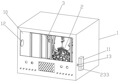
[0044] like figure 1 The shown experimental system for extreme high temperature thermal strength of complex curved structures for aerospace aircraft testing includes a micro-oxygen environment control system 1, which is set in the micro-oxygen environment control system 1 for heating the multi-temperature area extreme high temperature heating of the curved surface parts of the aircraft. Device 2, a loading device 3 arranged in the micro-oxygen environment control system 1 for applying a load to the aircraft curved surface part;

[0045] The micro-oxygen environment control system 1 includes a gas-tight cabin 10, a protective gas input device 11 communicated with the gas-tight cabin 10, an oxygen content monitoring system 12 disposed in the gas-tight cabin 10, and an oxygen content monitoring system 12 disposed in the gas-tight cabin 10. The gas pressure relief valve 13 on the gas-tight cabin 10;

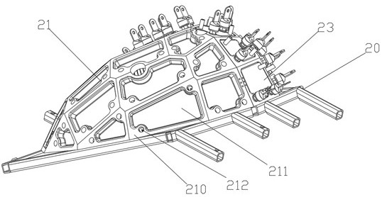
[0046] like figure 2 As shown, the multi-temperature zone extreme high temper...

Embodiment 2

[0065] The difference from Example 1 is that:

[0066] The length of the inner space of the radiation heating device 22 is 5m, the width is 4m, and the height is 5m.

[0067] The thickness of the graphite heating plate is 8 mm; the gap between adjacent graphite heating plates is 6 mm.

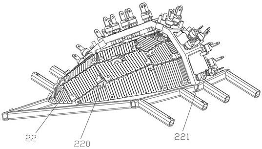
[0068] like Figure 7 As shown, the high temperature and high current composite electrode 221 includes an insulating sleeve 222 arranged in the mounting hole 212, a conductive column 223 arranged in the insulating sleeve 222 and connected to the heating plate 220 at one end, arranged in the insulating sleeve 222. The copper terminal 224 at the other end of the conductive column 223;

[0069] Both ends of the conductive post 223 are connected with boss threads 225;

[0070] The conductive posts 223 are respectively connected to the red copper terminals 224 and the heating plate 220 through the boss threads 225;

[0071] A water cooling circuit 226 is arranged in the red copper terminal 224 ....

Embodiment 3

[0074] The difference from Example 1 is:

[0075] The length of the inner space of the radiation heating device 22 is 3.5 m, the width is 3 m, and the height is 3 m.

[0076] The modular heating unit 210 is a metal copper plate;

[0077] The thickness of the graphite heating plate is 5 mm; the gap between adjacent graphite heating plates is 4 mm.


PUM


Abstract

The invention relates to the technical field of aircraft testing, in particular to a complex curved surface structure extreme high-temperature thermal intensity experiment system for aerospace aircraft testing, which comprises a micro-aerobic environment control system and a multi-temperature-zone extreme high-temperature heating device arranged in the micro-aerobic environment control system and used for heating aircraft curved surface components, the loading device is arranged in the micro-aerobic environment control system and is used for applying a load to the aircraft curved part; the multi-temperature-zone extreme high-temperature heating device comprises a control connecting frame arranged in the gas sealing cabin body, a high-reflectivity heating cover arranged on the control connecting frame, a radiation heating device arranged on the inner wall of the high-reflectivity heating cover, and a cooling device arranged on the outer wall of the high-reflectivity heating cover; according to the device, the curved surface part of the aircraft can enter an extreme thermal field environment with high temperature change speed and high temperature peak value, and the thermal field change of the aircraft in a high-altitude ultrahigh-speed flight state can be really simulated.

Description

technical field [0001] The invention relates to the technical field of aircraft testing, in particular to an extreme high temperature thermal strength experimental system for a complex curved surface structure used for aerospace aircraft testing. Background technique [0002] When the aerospace plane flies at hypersonic speed in the atmosphere, its structural surface is subjected to severe aerodynamic heating. The aerodynamic heating temperature peak is high, the temperature change rate is large, and the thermal field is extremely complex, which makes the structural thermal strength test in the aerospace plane strength test. It is extremely challenging to evaluate and evaluate the complex surface temperature and heat flow field distribution with local temperature exceeding 1800°C and temperature variation exceeding 200°C / s, it is difficult for the existing traditional experimental techniques to meet the experimental simulation requirements at the same time. [0003] The exis...

Claims


Application Information

Patent Timeline
Patent Type & Authority Applications(China)
IPC IPC(8): B64F5/60H05B3/20G01M99/00
CPCB64F5/60H05B3/20G01M99/00
Inventor 王彬文王铁军秦强李军鹏王振亚
Owner CHINA AIRPLANT STRENGTH RES INST
Learn More