
Load scheduling distribution method and platform for multi-furnace multi-machine complex production system

A production system and load scheduling technology, applied in the direction of complex mathematical operations, genetic rules, computer-aided design, etc., to achieve the effects of reducing frequent load changes, maximizing production profits, and minimizing energy consumption of equipment in operation

Pending Publication Date: 2022-06-03
浙江英集动力科技有限公司
View PDF0 Cites 2 Cited by
  • Summary
  • Abstract
  • Description
  • Claims
  • Application Information

AI Technical Summary

Problems solved by technology

At present, the boiler load distribution and turbine load distribution strategies are relatively simple. By sending the total load command to each boiler controller after being weighted by the load distribution coefficient, few researchers take into account the multi-boiler and multi-machine scenarios for different fuels and the economical and environmental protection. , energy consumption and other multi-objective optimal scheduling

Method used


Image

  • Load scheduling distribution method and platform for multi-furnace multi-machine complex production system
  • Load scheduling distribution method and platform for multi-furnace multi-machine complex production system
  • Load scheduling distribution method and platform for multi-furnace multi-machine complex production system

Examples


Embodiment 1

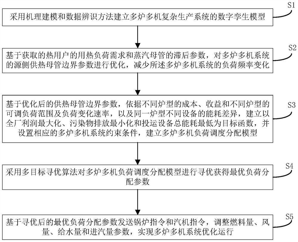
[0153] figure 1 It is a flow chart of the load scheduling and distribution method of the multi-furnace and multi-machine complex production system involved in the present invention.

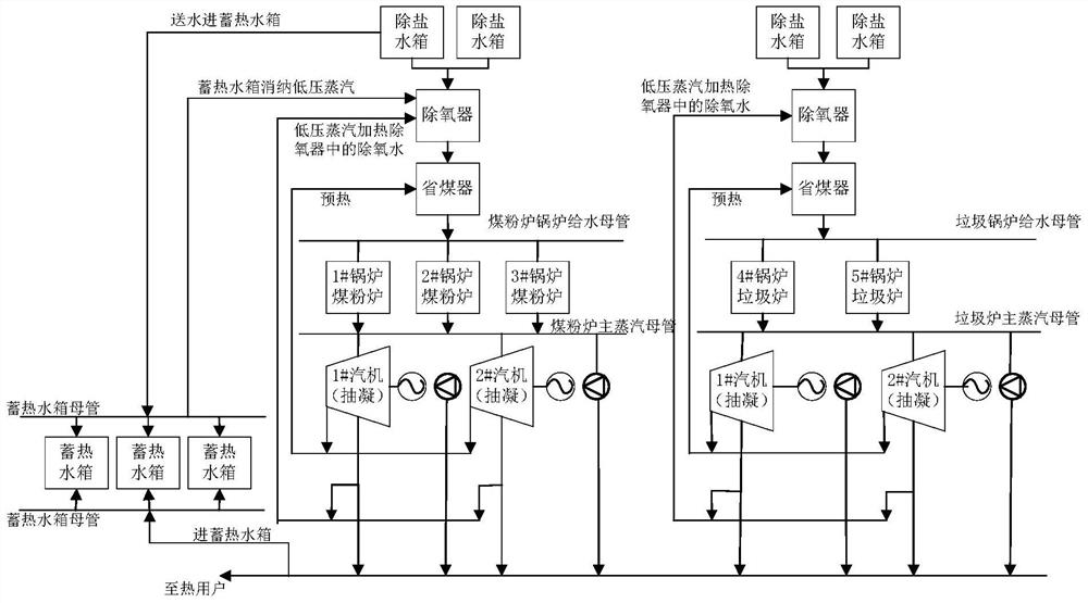
[0154] figure 2 It is a schematic diagram of the multi-furnace and multi-machine complex production system involved in the present invention.

[0155] like figure 1 , 2 As shown, the present embodiment 1 provides a load scheduling and distribution method for a multi-furnace and multi-machine complex production system, which includes:

[0156] Step S1, using mechanism modeling and data identification methods to establish a digital twin model of a multi-furnace multi-machine complex production system;

[0157] Step S2, based on the obtained heat load demand of the heat user and the lag parameter of the steam main pipe, optimize the boundary parameters of the source side heating main pipe of the multi-boiler and multi-machine system, so as to reduce the load frequency of the multi-boiler and mu...


PUM


Abstract

The invention discloses a load dispatching distribution method for a multi-furnace multi-machine complex production system. The method comprises the following steps: establishing a digital twin model of the multi-furnace multi-machine complex production system by adopting a mechanism modeling and data identification method; optimizing boundary parameters of a source side heat supply mother pipe of the multi-furnace multi-machine system based on the obtained heat consumption load requirements of the heat users and heat storage and lag parameters of the heat supply network; on the basis of the optimized boundary parameters of the heat supply mother pipe, according to the cost and income of different furnace types, the adjustable load range and load change rate of different furnace types and the energy consumption difference of different devices of the same furnace type, a target function with maximization of the profit of the whole plant, minimization of pollutant emission and minimum total energy consumption of the devices put into operation is established; corresponding multi-furnace multi-machine system constraint conditions are set, and a multi-furnace multi-machine load dispatching distribution model is established; carrying out optimization by adopting a multi-target optimization algorithm to obtain an optimal load distribution parameter; and sending a boiler instruction and a steam turbine instruction based on the optimized optimal load distribution parameter.

Description

technical field [0001] The invention belongs to the technical field of intelligent heating, and in particular relates to a load scheduling and distribution method and platform for a multi-furnace and multi-machine complex production system. Background technique [0002] Generally, the turbines and boilers of small thermal power plants are relatively independent, with only simple signal exchange. The coordinated control between the turbines and boilers is mostly completed by oral notification and manual operation. Most thermal power companies also have the characteristics of small furnace capacity, large number of units, and large thermal load fluctuations. When generating electricity at the same time as central heating, it is necessary to ensure the heating pressure and power generation load at the same time. This situation makes the operating conditions of the whole plant compare. It is complicated, and the load allocation is more difficult than that of unit units. In orde...

Claims


Application Information

Patent Timeline
IPC IPC(8): G06F30/27G06F30/28G06F17/13G06N3/12G06Q10/04G06Q50/06G06F119/08G06F119/06G06F113/04
CPCG06F30/27G06F30/28G06F17/13G06N3/126G06Q10/04G06Q50/06G06F2119/08G06F2119/06G06F2113/04Y02P90/02
Inventor 刘成刚穆佩红时伟谢金芳
Owner 浙江英集动力科技有限公司
Learn More