Forming cutter for sputtering target material sealing groove and grooving method of forming cutter

A technology of sputtering target material and slotting method, which is applied in the direction of milling cutters, metal processing equipment, milling machine equipment, etc., can solve the problem of unspecified O-shaped seal groove diameter consistency, etc., to improve the processing effect and improve processing efficiency , High slotting efficiency and precision effect

Pending Publication Date: 2022-06-03
KONFOONG MATERIALS INTERNATIONAL CO LTD
View PDF12 Cites 0 Cited by
  • Summary
  • Abstract
  • Description
  • Claims
  • Application Information

AI Technical Summary

Problems solved by technology

[0004] CN204849010U discloses a magnetron sputtering target capable of externally adjusting the magnetic field, mainly comprising a target body and a magnetizer, the lower end of the target body is provided with a through hole, and an adjustment shaft is arranged in the target body, and the lower end of the adjustment shaft is located in the through hole Inside, the lock nut is installed in the through hole through the pressure sleeve III and fixed with the lower end of the adjustment shaft. The adjustment shaft is provided with a pressure sleeve I and a pressure sleeve II, and there is an O between the pressure sleeve I and the pressure sleeve II. The pressure sleeve I is located above the pressure sleeve II. The pressure sleeve I is fixed in the target body by bolts. There is an O-shaped sealing ring between the pressure sleeve I and the target body. The magnetizer is installed on the adjustment shaft through an adjustable support plate. Above, the magnet guide is installed on the adjustable support plate through studs and fixed by nuts; none of the above documents gives the technical content on how to improve the consistency of the O-ring seal groove diameter

Method used


Image

  • Forming cutter for sputtering target material sealing groove and grooving method of forming cutter
  • Forming cutter for sputtering target material sealing groove and grooving method of forming cutter

Examples


Embodiment Construction

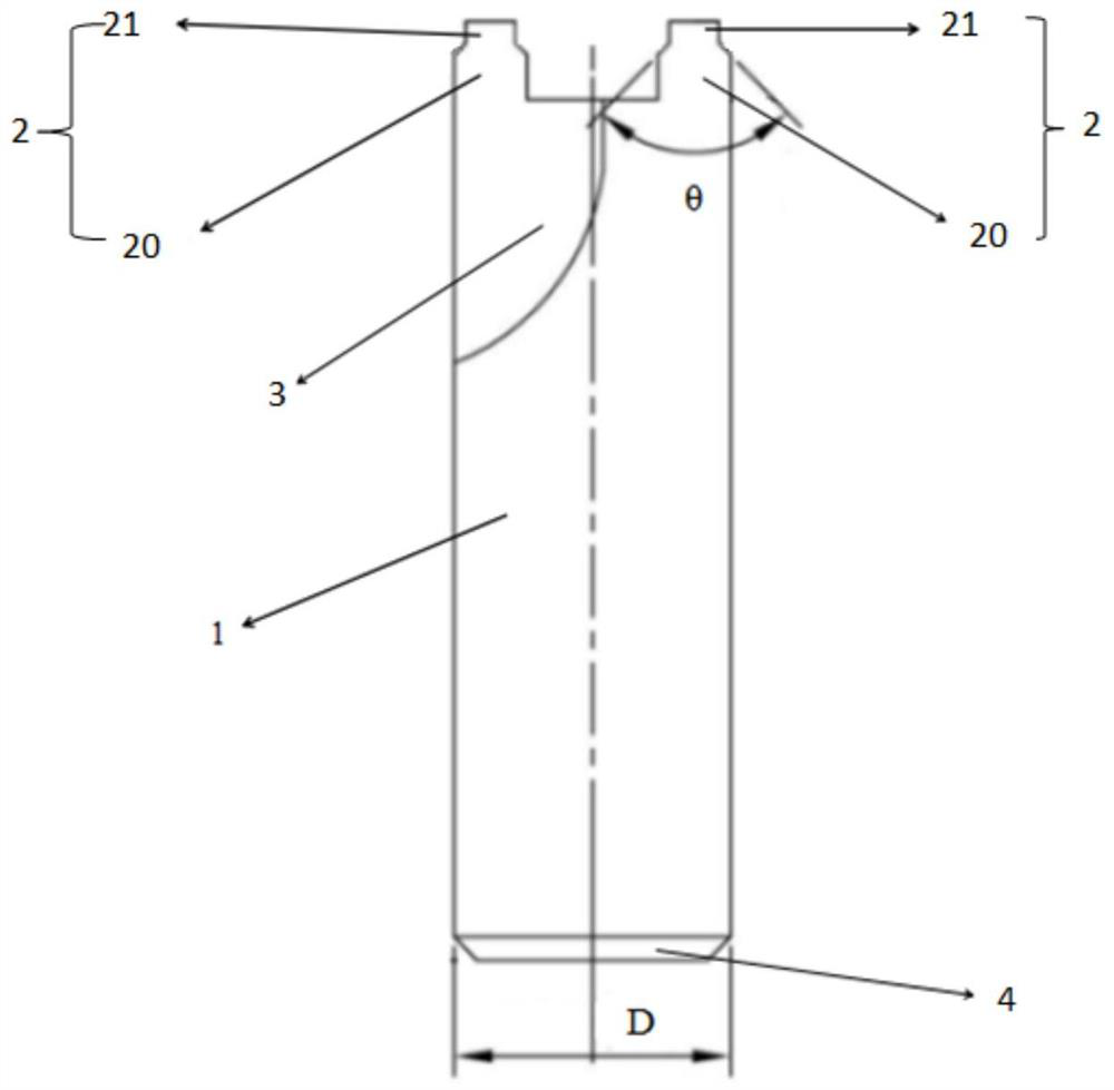
[0047] It should be understood that in the description of the present invention, the terms "center", "portrait", "horizontal", "top", "bottom", "front", "rear", "left", "right", " The orientation or positional relationship indicated by vertical, horizontal, top, bottom, inner, outer, etc. is based on the orientation or positional relationship shown in the drawings, and is only for the convenience of describing the present invention and The description is simplified rather than indicating or implying that the device or element referred to must have a particular orientation, be constructed and operate in a particular orientation, and therefore should not be construed as limiting the invention. In addition, the terms "first", "second", etc. are used for descriptive purposes only, and should not be construed as indicating or implying relative importance or implying the number of indicated technical features. Thus, a feature defined as "first", "second", etc., may expressly or impl...


PUM


Abstract

The invention relates to a forming cutter of a sputtering target material sealing groove and a grooving method of the forming cutter, the forming cutter comprises a cylindrical cutter bar, the end face of the cutter bar is provided with protrusions, the protrusions are distributed on an annular area with the central axis of the cutter bar as the center line, and a chip groove is formed between every two adjacent protrusions; the forming cutter is used for the grooving process of the O-shaped sealing groove of the sputtering target material, the rotating speed and the feeding amount of the forming cutter are controlled, various errors generated in the machining process can be effectively avoided, and therefore the consistency of the diameter of the O-shaped sealing groove can be kept, and the efficiency of the grooving process is improved.

Description

technical field [0001] The invention belongs to the field of sputtering target material processing, and relates to a forming knife for sealing grooves of a sputtering target material and a method for grooving the same. Background technique [0002] The sputtering target sealing groove is the most critical place in the use of the target, which can ensure that there is no leakage of air and water during the use of the sputtering target, and avoid damage to the sputtering machine during the sputtering process. In the process of machining the sealing groove of the target material, the end mill is used for machining, and there will be tool measurement errors, machine tool alignment errors, and errors in each measurement in each machining process; this will result in poor consistency of the diameter of the O-shaped sealing groove obtained. question. [0003] CN101935823A discloses a magnetron sputtering target, which includes a target cathode and a target anode, the target anode ...

Claims


Application Information

Patent Timeline
Patent Type & Authority Applications(China)
IPC IPC(8): B23C5/10B23C5/16B23C3/28
CPCB23C5/10B23C5/165B23C3/28
Inventor 姚力军潘杰边逸军王学泽钱百峰
Owner KONFOONG MATERIALS INTERNATIONAL CO LTD
Why Eureka
Try Eureka