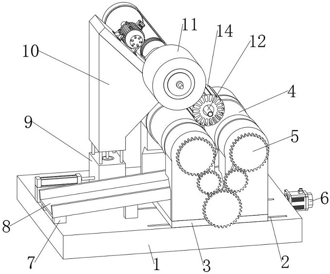
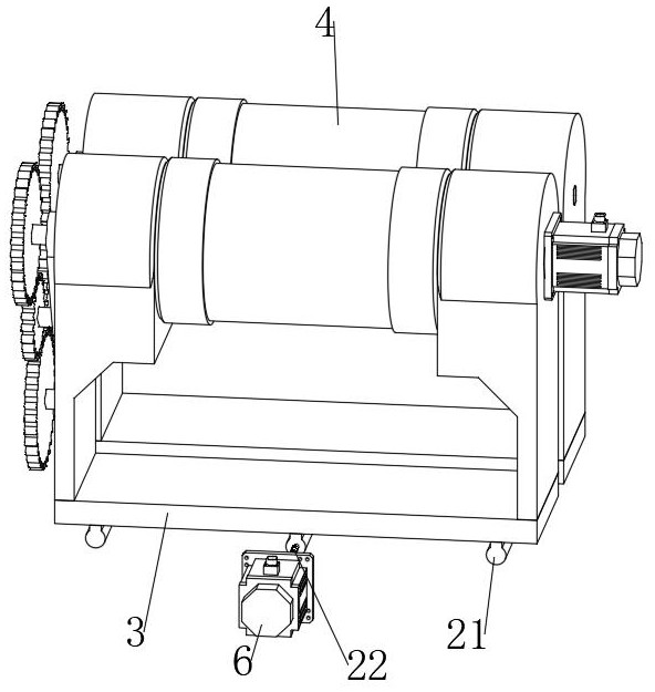
A surface polishing device for motor rotor production

A surface polishing and motor rotor technology, which is applied to surface polishing machine tools, grinding drive devices, grinding/polishing equipment, etc., can solve the problem of increasing production costs, increasing the difficulty of loading and unloading motor rotors, increasing Solve problems such as labor load of operating workers to achieve the effect of improving operating efficiency

Active Publication Date: 2022-07-22
SICHUAN FUSHENG ELECTRIC APPLIANCE CO LTD
View PDF4 Cites 0 Cited by
  • Summary
  • Abstract
  • Description
  • Claims
  • Application Information

AI Technical Summary

Problems solved by technology

[0003] The existing surface polishing devices for motor rotor production have the following disadvantages: 1. Most of the existing surface polishing devices for motor rotor production need to fix the motor rotor and make the motor rotor rotate to ensure that the surface of the motor rotor is fully polished. The difficulty of loading and unloading the motor rotor is increased, and operators are required to manually install and fix the motor rotor, which reduces the polishing efficiency and is not conducive to the polishing of large quantities of motor rotors; 2. The existing motor rotor production surface Most of the polishing devices do not polish the inner hole wall of the motor rotor, that is, after the surface polishing of the motor rotor is completed, additional inner hole wall polishing is required, which increases the production cost; 3. The existing surface polishing device for motor rotor production Most of them require operators to manually pick up materials, which increases the workload of operators and is not conducive to assembly line operations. Therefore, we propose a surface polishing device for motor rotor production.

Method used


Image

  • A surface polishing device for motor rotor production
  • A surface polishing device for motor rotor production
  • A surface polishing device for motor rotor production

Examples


Embodiment Construction

[0034] In order to make the technical means, creative features, achievement goals and effects realized by the present invention easy to understand, the present invention will be further described below with reference to the specific embodiments.

[0035] In the description of the present invention, it should be noted that the terms "upper", "lower", "inner", "outer", "front end", "rear end", "two ends", "one end" and "the other end" The orientation or positional relationship indicated by etc. is based on the orientation or positional relationship shown in the accompanying drawings, and is only for the convenience of describing the present invention and simplifying the description, rather than indicating or implying that the indicated device or element must have a specific orientation, with a specific orientation. The orientation configuration and operation are therefore not to be construed as limiting the invention. Furthermore, the terms "first" and "second" are used for desc...


PUM


Abstract

The invention discloses a surface polishing device for the production of a motor rotor, comprising a base, and three first sliding grooves arranged in parallel are opened on the right part of the upper end of the base, and two installations are arranged between the three first sliding grooves. The mounting racks have a U-shaped structure. The middle parts of the two mounting racks are provided with placing cylinders. The two placing cylinders are symmetrically distributed on the left and right. The front ends of the two mounting racks are jointly provided with a transmission mechanism. The transmission mechanism is connected to the placing cylinder through a transmission, a first motor is installed on the right end of the base, a number of support legs are installed on the upper end of the base, and a collection groove is installed on the upper ends of the support legs, and the collection groove is located at the front of the installation frame. left. During the polishing operation of the present invention, the motor rotor only needs to be placed on the placing cylinder, and the process of manually fixing the motor rotor is omitted. The surface and inner hole wall of the motor rotor of different sizes can be polished, and the automatic material receiving function , reduce production costs and improve polishing efficiency.

Description

technical field [0001] The invention relates to the technical field of motor rotor production, in particular to a surface polishing device for motor rotor production. Background technique [0002] The rotor is the rotating part of the motor, including the rotor core, the rotor winding and the rotating shaft. Among them, the rotor core is a part of the magnetic circuit of the motor, and the rotor winding is placed, which is generally punched and laminated by 0.5 mm thick silicon steel sheets. ; The rotor winding is used to cut the stator magnetic field to generate induced electromotive force and current, and under the action of the rotating magnetic field, the rotor is rotated by force; the rotating shaft is used to transmit torque and support the weight of the rotor. Due to the presence of burrs and uneven lines on the surface of the rotor of the motor just produced, the air gap between the stator and the rotor is increased, thereby increasing the reluctance, so that the no-...

Claims


Application Information

Patent Timeline
Patent Type & Authority Patents(China)
IPC IPC(8): B24B29/02B24B41/00B24B41/06B24B47/20B24B41/02H02K15/02
CPCB24B29/02B24B41/007B24B41/06B24B47/20B24B41/02H02K15/02Y02P70/10
Inventor 马健陈忠许百宏佟德王森周正
Owner SICHUAN FUSHENG ELECTRIC APPLIANCE CO LTD
Why Eureka
Try Eureka