
Full-rigid-connection orthogonal laminated wood coupled shear wall based on steel plate constraint

A technology of glued wood and shear wall, applied in the direction of building types, buildings, building components, etc., can solve the problems of easy splitting and damage of screw hole wood, small residual deformation after earthquake, and high degree of assembly, so as to improve the transverse grain Splitting damage, convenient construction, high degree of assembly effect

Pending Publication Date: 2022-05-20
TONGJI UNIV
View PDF0 Cites 0 Cited by
  • Summary
  • Abstract
  • Description
  • Claims
  • Application Information

AI Technical Summary

Problems solved by technology

[0004] The purpose of the present invention is to provide an anti-lateral rigidity and post-earthquake residual deformation in order to overcome the above-mentioned insufficient lateral rigidity of the existing cross-glued timber shear wall, and the problems that the horizontal grains of the wood screw holes are easily cracked and damaged under pressure. The fully rigid-jointed orthogonal glulam combined shear wall is small, highly assembled, and the beam ends and wall toes are constrained by steel plates. The lateral stiffness of the shear wall is enhanced by wrapping the joint area and the wall toe with outsourcing steel plates. and improved the problem that the wood under screw holes is prone to splitting and damage, and at the same time, the structure of the double-limb shear wall meets the needs of opening holes in the external wall

Method used


Image

  • Full-rigid-connection orthogonal laminated wood coupled shear wall based on steel plate constraint
  • Full-rigid-connection orthogonal laminated wood coupled shear wall based on steel plate constraint
  • Full-rigid-connection orthogonal laminated wood coupled shear wall based on steel plate constraint

Examples


Embodiment

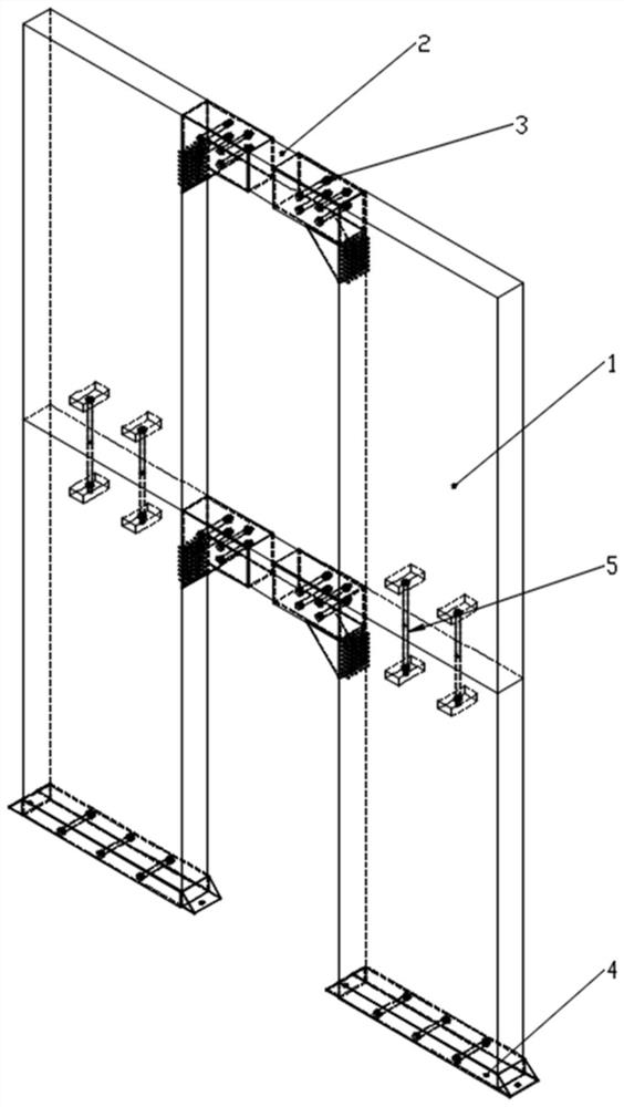
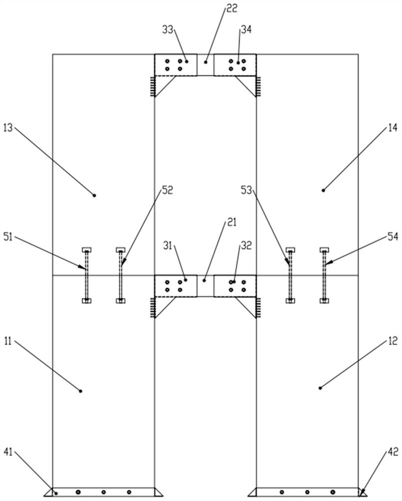
[0042] Combined with the above structure description, the shear wall of this embodiment is made. The shear wall is used in the two-story cross-glued wood structure, the floor height is 2.6m, the total height is 5.2m, the total length of the double-leg shear wall is 3600mm, and the thickness is 195mm; The length of the wall plinth is 1200mm, the length of the connecting beam is 1200mm, the cross-sectional size of the connecting beam is 175mm×250mm, and there is a gap of 5mm between the connecting beam and the wall pier to prevent the secondary stress caused by the expansion of the wood. Made of 250mm cross-laminated wood, 4 bolt holes with a diameter of 24mm are pre-opened at each end.

[0043] The cross-laminated timber wall limbs are prefabricated in the factory. Bolt holes with a diameter of 24mm are pre-opened at the bottom of the first-story shear wall, and two 100mm×50mm square holes are opened at the upper part 300mm from the top surface. The second-story shear wall Two ...


PUM


Abstract

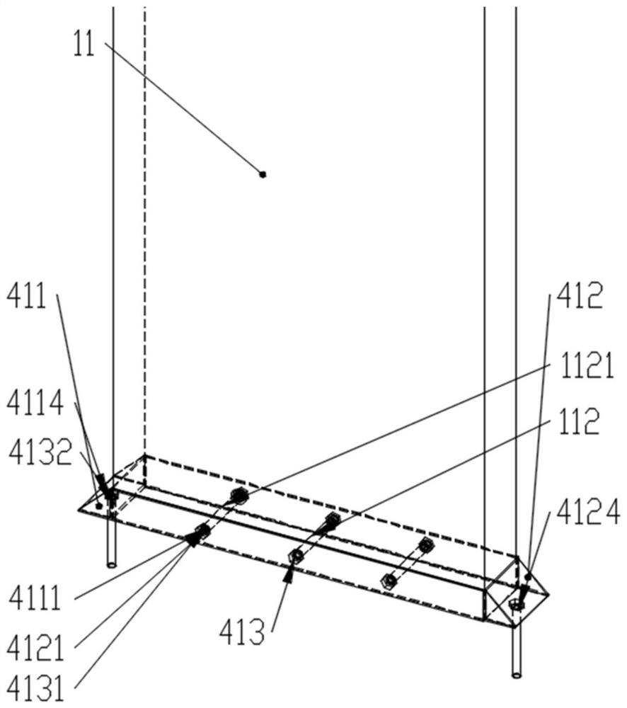
The invention relates to a full-rigid connection orthogonal laminated wood coupled shear wall based on steel plate constraint, the shear wall is of a multi-layer structure from bottom to top, and each layer of structure comprises two orthogonal laminated wood shear walls which are transversely connected through a laminated wood coupling beam; the left beam end and the right beam end of the laminated wood coupling beam are fixedly connected with the orthogonal laminated wood shear walls through the connecting pieces of the orthogonal laminated wood wall columns and the coupling beam respectively, and the two orthogonal laminated wood shear wall toes in the lowermost layer structure are fixedly connected with the foundation through the connecting pieces of the orthogonal laminated wood wall columns and the foundation. And the orthogonal laminated wood shear walls at the corresponding positions in each layer of structure above the lowermost layer of structure are connected through high-strength bolts. The connecting structure has the advantages that the lateral resistance is good, the defect that wood at the bolt connecting position is prone to cross grain splitting damage is overcome, the rigidity of the connecting position of the shear wall and the connecting beam and the connecting position of the wall toe and the foundation are large, and the assembly degree is high.

Description

technical field [0001] The invention relates to the field of structural engineering wood structure buildings, in particular to a fully rigid-jointed orthogonal glued-laminated wood combined shear wall with both beam ends and wall toes constrained by steel plates, which is used for multi-storey buildings with high requirements for seismic performance Timber construction. Background technique [0002] Cross laminated timber (CLT for short) is a heavy-duty engineered wood. It is a prefabricated engineered wood panel made of at least 3 layers of solid wood sawn timber or structural composite panels orthogonally assembled with structural adhesives. It has the characteristics of high lateral stiffness, good bearing capacity, stable size, excellent two-way mechanical properties, environmental protection, and high degree of industrialization. It is often used in floor slabs and shear walls of multi-story wooden structures. The force wall will lose its anti-lateral bearing capacity ...

Claims


Application Information

Patent Timeline
Patent Type & Authority Applications(China)
IPC IPC(8): E04H9/02E04B1/98
CPCE04H9/021E04B1/98
Inventor 孙晓峰王重耳李征何敏娟舒展
Owner TONGJI UNIV
Learn More