Reinforced gear with high wear resistance
A wear resistance and gear technology, applied in gear transmission, gear lubrication/cooling, belt/chain/gear, etc., can solve problems such as reducing gear reliability, increasing gear transmission noise, and shortening gear service life. Achieve the effect of improving service life, reducing friction and improving wear resistance
- Summary
- Abstract
- Description
- Claims
- Application Information
AI Technical Summary
Problems solved by technology
Method used
Image
Examples
Embodiment 1
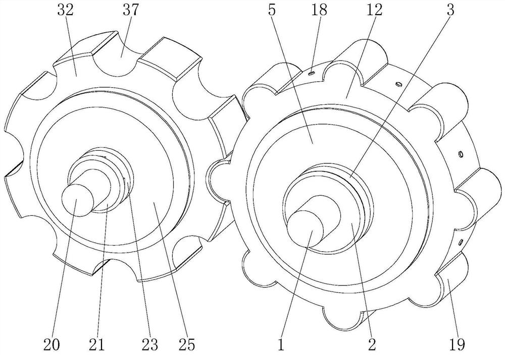
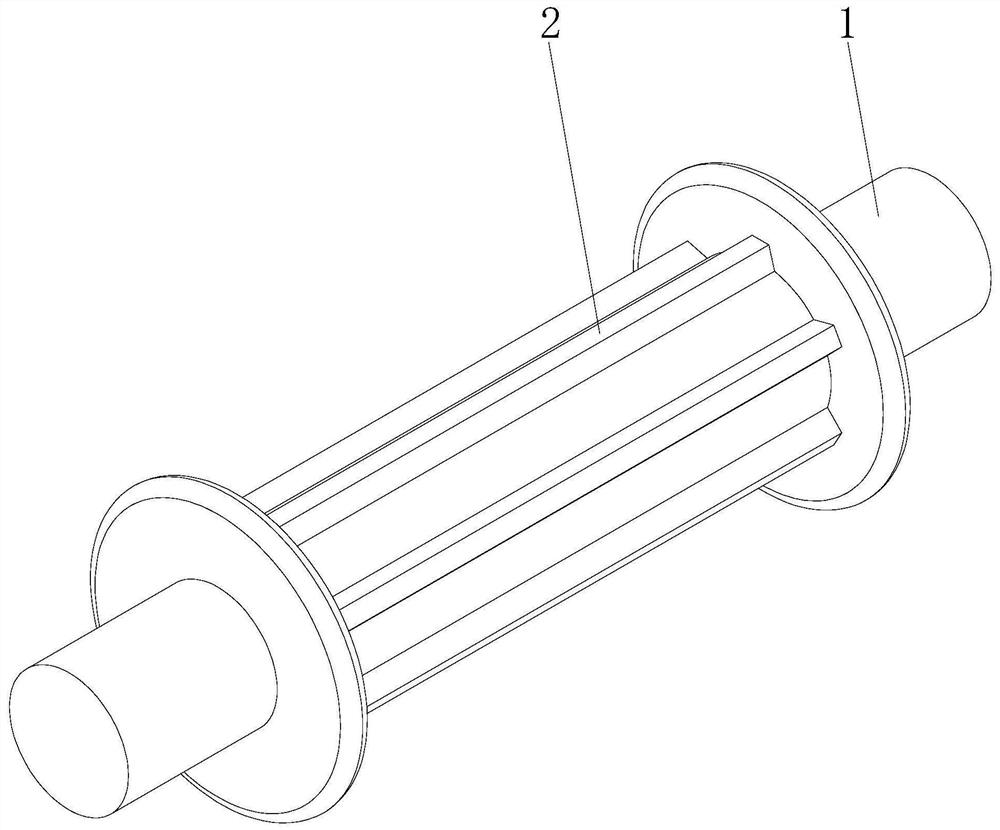
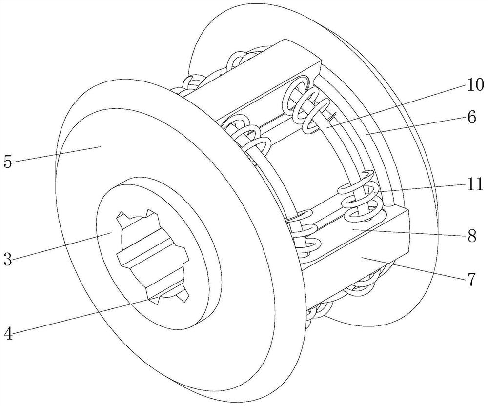
[0036] see Figure 1-14 , the present invention provides a technical solution: a reinforced gear with high wear resistance, including an active rod 1, a passive rod 20 and a gear bar 38, the outer movable part of the active rod 1 is connected with an active inner runner 3, and the active inner rotation The outside of the wheel 3 is fixedly sleeved with active left and right baffles 5, the inner side of the active left and right baffles 5 is fixedly installed with an active slip ring 6, and the outside of the active inner runner 3 is fixedly installed with a buffer block 7, and the two sides of the buffer block 7 are provided with There is a first placement groove 8, and a first through groove 9 is opened inside the first placement groove 8, and a limit ring 10 is movable installed inside the first through groove 9, and a buffer spring is movably sleeved on the outside of the limit ring 10 11. The active outer runner 12 is sleeved on the outer movable part of the active inner r...
Embodiment 2
[0039] Such as Figure 1-14 As shown, on the basis of Embodiment 1, the present invention provides a technical solution: the active rod 1 is fixedly sleeved with an active limiting plate 2, and the active inner runner 3 is provided with an active card slot 4, There are two active left and right baffles 5, and the two active left and right baffles 5 are symmetrically and fixedly sleeved on the outside of the active inner runner 3. , the active slip ring 6 is fixedly installed on the opposite sides of the two active left and right baffle plates 5 respectively, the active slip ring 6 is compatible with the size of the limit chute 14 and the position is corresponding, there are four buffer blocks 7, four A buffer block 7 is circumferentially fixedly installed on the outside of the active inner runner 3, there are two first through grooves 9, and the two first through grooves 9 symmetrically run through the buffer block 7, there are four limit blocks 13, and the four limit blocks ...
Embodiment 3
[0042] Such as Figure 1-14 As shown, on the basis of Embodiment 1 and Embodiment 2, the present invention provides a technical solution: two passive limiting plates 21 are fixedly installed on the outside of the passive rod 20, and passive limiting plates 21 are fixedly installed on the outside of the passive rod 20. Card block 22, the inside of passive inner runner 23 is provided with passive card slot 24, and the size of passive card slot 24 and passive card block 22 is adapted and the position is corresponding, and passive left and right baffle plate 25 has two, two passive The left and right baffles 25 are symmetrically movably socketed on the outside of the passive inner runner 23, the passive slip ring 26 is compatible with the specifications and sizes of the passive chute 34 and their positions are corresponding, and there are two shock absorbing blocks 27, two shock absorbing blocks 27 are circumferentially arranged on the outside of the passive inner runner 23, and t...
PUM
 Abstract
Description
Claims
Application Information
 - R&D Engineer
- R&D Manager
- IP Professional
- Industry Leading Data Capabilities
- Powerful AI technology
- Patent DNA Extraction
Browse by: Latest US Patents, China's latest patents, Technical Efficacy Thesaurus, Application Domain, Technology Topic, Popular Technical Reports.
© 2024 PatSnap. All rights reserved.Legal|Privacy policy|Modern Slavery Act Transparency Statement|Sitemap|About US| Contact US: help@patsnap.com


