
Arched abutment structure and construction method thereof

A construction method and arch bridge technology, which can be applied to basic structure engineering, underwater structures, bridges, etc., can solve problems such as easy deformation, difficult to meet crossing requirements, overturning deformation, etc., and achieve the effect of improving stability

Pending Publication Date: 2022-05-17
GUANGDONG METALLURGICAL & ARCHITECTURAL DESIGN INST
View PDF0 Cites 0 Cited by
  • Summary
  • Abstract
  • Description
  • Claims
  • Application Information

AI Technical Summary

Problems solved by technology

[0003] At present, the common abutment structures in urban bridges include thin-walled abutments, ribbed abutments and buttressed abutments, etc., but these traditional abutments have the disadvantage of weak lateral spanning ability due to structural limitations. When the bridge needs to cross the subway When constructing the structure, since pile foundation construction is prohibited within a certain range around the subway, the abutment structure needs to span tens of meters in one go, and the middle part of the abutment is prone to deformation or even fracture due to lack of support
At this time, the conventional abutment design is difficult to meet the spanning requirements, and it is prone to overturning deformation due to the lateral extrusion force of the fill soil behind the abutment

Method used


Image

  • Arched abutment structure and construction method thereof
  • Arched abutment structure and construction method thereof
  • Arched abutment structure and construction method thereof

Examples


Embodiment Construction

[0031] This part will describe the specific embodiment of the present invention in detail, and the preferred embodiment of the present invention is shown in the accompanying drawings. Each technical feature and overall technical solution of the invention, but it should not be understood as a limitation on the protection scope of the present invention.

[0032] In the description of the present invention, it should be understood that the orientation descriptions, such as up, down, front, back, left, right, etc. indicated orientations or positional relationships are based on the orientations or positional relationships shown in the drawings, and are only In order to facilitate the description of the present invention and simplify the description, it does not indicate or imply that the device or element referred to must have a specific orientation, be constructed and operated in a specific orientation, and thus should not be construed as limiting the present invention.

[0033] I...


PUM


Abstract

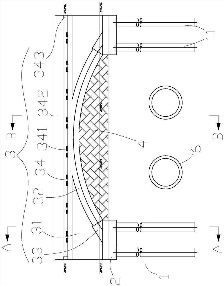
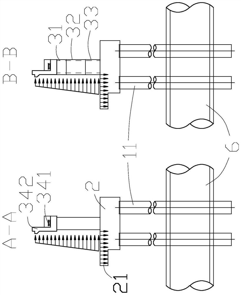
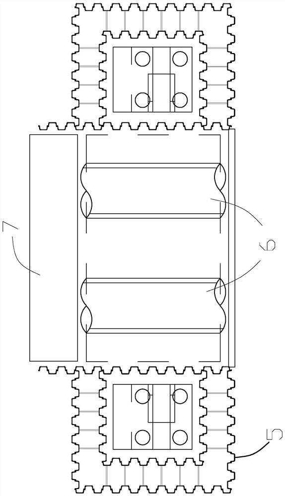
The invention discloses an arched bridge abutment structure and a construction method thereof. The arched bridge abutment structure comprises two groups of pile foundations, the two bearing platforms are arranged in one-to-one correspondence with the two sets of pile foundations, one ends of the pile foundations are connected with the bearing platforms, the bearing platforms are provided with ballasting plates, the ballasting plates protrude out of the bearing platforms, and the ballasting plates are used for filling soil behind the bearing platforms; the platform body comprises a platform body and an arch rib, the platform body is connected with the bearing platforms, the platform body and the ballasting plate form an L-shaped structure, the two ends of the arch rib are connected to the two bearing platforms respectively, and the rise span ratio of the arch rib ranges from 0.222 to 0.125; and the retaining wall is connected with the arch rib and is used for filling a cavity below the arch rib so as to prevent a soil body behind the abutment from sliding off. According to the invention, the arch-shaped abutment body is arranged and straddled on the existing subway line, so that the construction of the abutment can be carried out under the condition that the operation of the existing subway is not influenced; the ballasting plate and the abutment body form an L-shaped structure, so that the gravity part of filling soil behind the abutment can be partially converted into resistance for resisting the lateral soil pressure of the filling soil, and the stability of the abutment is improved.

Description

technical field [0001] The invention relates to an arched abutment structure and a construction method thereof in the field of civil engineering bridges. Background technique [0002] In recent years, with the continuous development of urban construction, the urban infrastructure has also been continuously improved. Therefore, the construction of bridges and other transportation facilities in cities with basically complete infrastructure will often be restricted by some boundary conditions. For example, common constraints include subway structures and underground pipelines. How to better build bridges under these constraints is of great significance to urban development. [0003] At present, the common abutment structures in urban bridges include thin-walled abutments, ribbed abutments and buttressed abutments, etc., but these traditional abutments have the disadvantage of weak lateral spanning ability due to structural limitations. When the bridge needs to cross the subway ...

Claims


Application Information

Patent Timeline
IPC IPC(8): E01D19/02E01D19/00E01D21/00E02D27/12E02D27/14E02D29/045E02D17/00E02D17/04E02D29/02E02D17/18E02D5/04
CPCE01D19/02E01D19/00E01D21/00E02D27/12E02D27/14E02D29/045E02D17/00E02D17/04E02D29/02E02D17/18E02D5/04Y02A30/60
Inventor 李炎解冰方万进周浩霖李真颜赖苑林曲研
Owner GUANGDONG METALLURGICAL & ARCHITECTURAL DESIGN INST
Learn More