Satellite layout based on joint detection of multiple types of remote sensing instruments

A multi-type, remote sensing technology, applied in the field of spacecraft, can solve problems such as insufficiency, and achieve the effect of reducing the satellite center of mass, improving the mechanical environment, and expanding the load carrying capacity

Active Publication Date: 2022-05-17
SHANGHAI SATELLITE ENG INST
View PDF11 Cites 0 Cited by
  • Summary
  • Abstract
  • Description
  • Claims
  • Application Information

AI Technical Summary

Problems solved by technology

[0004] The satellite layout in the above related papers and patents cannot meet the application requirements of the three active radar loads of laser radar, millimeter wave radar and terahertz radar and the common platform placement of optical imaging instruments to realize the joint detection of multiple types of remote sensing instruments

Method used


Image

  • Satellite layout based on joint detection of multiple types of remote sensing instruments
  • Satellite layout based on joint detection of multiple types of remote sensing instruments
  • Satellite layout based on joint detection of multiple types of remote sensing instruments

Examples


Embodiment 1

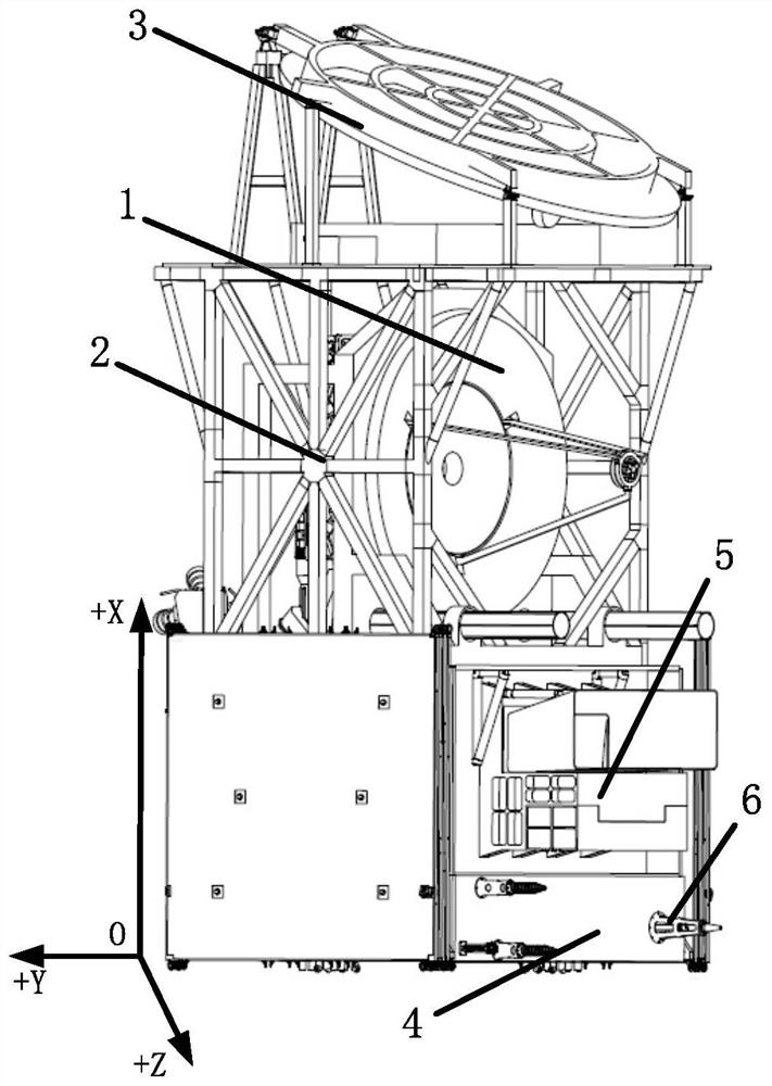
[0038] The present invention provides a satellite layout based on the joint detection of multi-type remote sensing instruments, including a satellite platform 4. For convenience of description, the satellite layout coordinate system O-XYZ is first established, such as figure 1 As shown, the definition is as follows:

[0039] Coordinate origin O: the center of the separation plane between the satellite and the launch vehicle;

[0040] Z axis: The satellite is in orbit along the coordinate origin O pointing to the direction of the earth;

[0041] X-axis: point to the direction of the platform along the origin O of the coordinates, and keep in line with the flight direction of the satellite;

[0042] Y axis: It forms a right-hand system with the X and Z axes.

[0043] Specifically, the top of the satellite platform 4 is respectively installed with a laser / millimeter-wave radar 1 and a terahertz radar 3 through a first installation frame and a second installation frame, and the ...

Embodiment 2

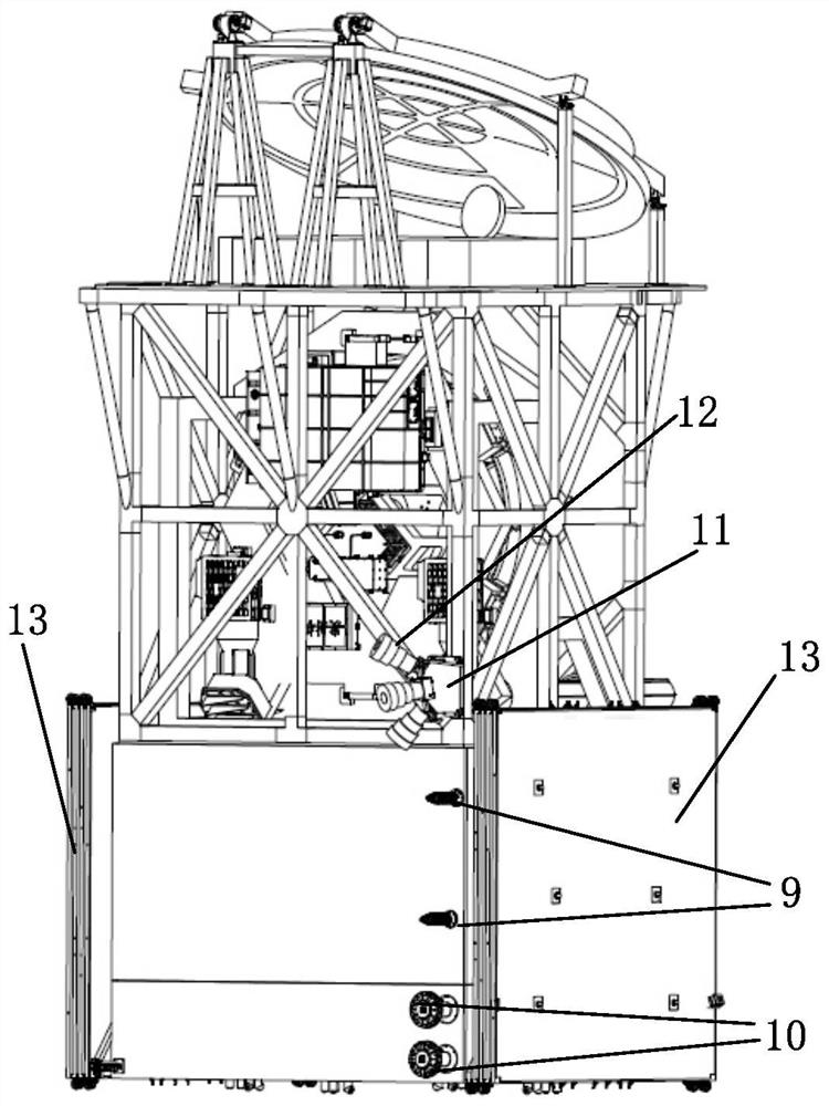
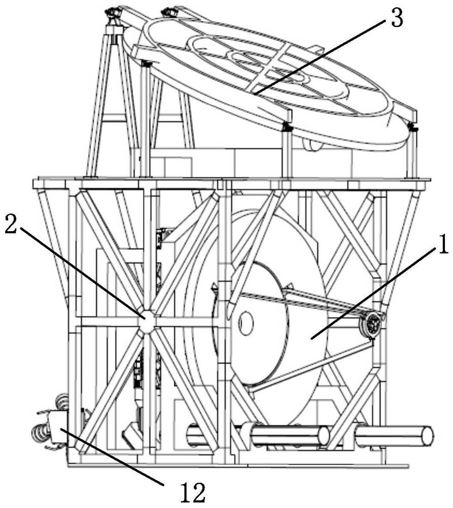
[0047] This embodiment is a preferred example of Embodiment 1.

[0048] In this example, if figure 2 , image 3 , Figure 4 , Figure 5 As shown, the first installation frame adopts a truss structure 2, and one end of the truss structure 2 is connected to the top of the satellite platform 4 and forms an accommodation space with the satellite platform 4, and the terahertz radar 3 is installed on At the other end of the truss structure 2, the second mounting frame adopts an aluminum alloy frame, and the laser / millimeter wave radar 1 is arranged in the accommodation space and installed on the top of the satellite platform 4 through the aluminum alloy frame.

[0049]The terahertz radar 3 adopts a main reflector with a diameter of 2m, which is folded when the satellite is launched and unfolded after entering orbit. When the main reflector of the terahertz radar 3 is in the unfolded state, the main reflector and the top surface of the satellite platform 4 The included angle is ...


PUM


Abstract

The invention provides a satellite layout based on joint detection of multiple types of remote sensing instruments, which comprises a satellite platform, a laser / millimeter wave radar and a terahertz radar are respectively mounted at the top of the satellite platform through a first mounting rack and a second mounting rack, and a thruster unit is mounted at the bottom of the satellite platform. A first side face, a second side face, a third side face and a fourth side face are sequentially arranged on the peripheral side of the satellite platform, an optical imaging detection instrument, an earth data transmission antenna, an earth measurement and control antenna and a sun sensor are arranged on the first side face, and an antenna measurement and control antenna and a navigation receiving antenna are arranged on the third side face. According to the invention, three active radar loads, namely the laser radar, the millimeter wave radar and the terahertz radar, and an optical imaging instrument are arranged on the same platform, so that the application requirement of joint detection of multiple types of remote sensing instruments is met.

Description

technical field [0001] The invention relates to the technical field of spacecraft, in particular to a satellite layout based on joint detection of multiple types of remote sensing instruments. Background technique [0002] With the continuous development and upgrading of space-based remote sensing observation tasks in my country's meteorology, environment, ocean, land and resources and other application fields, the volume and quality of remote sensing instruments are getting larger and larger, the types of remote sensing instruments are increasing, and the classification of detection elements is getting better and better. As the data becomes more and more detailed, the demand for joint detection of the same detection element by multiple types of remote sensing instruments is becoming more and more urgent. Under the constraints of the launch capability of the existing mature launch vehicle and the envelope of the fairing, the overall layout of the satellite requires an increas...

Claims


Application Information

Patent Timeline
Patent Type & Authority Applications(China)
IPC IPC(8): B64G1/10B64G1/66B64G1/44B64G1/22G01S13/86G01S17/86
CPCB64G1/1021B64G1/66B64G1/443B64G1/222G01S13/86G01S13/865G01S13/867G01S17/86B64G1/1035B64G1/1028Y02A90/10
Inventor 潘高伟丁丕满张宏伟袁野王志国缪鹏飞徐天水袁金如马晶晶
Owner SHANGHAI SATELLITE ENG INST
Why Eureka
Try Eureka