Filling body self-rotation stirring device and process thereof

A stirring device and rotary stirring technology, which can be used in fillings, safety devices, mining equipment, etc., can solve the problems of safety accidents, high pressure on the occupied area and high investment, and achieve the effects of high safety, small occupied area and low cost.

Pending Publication Date: 2022-05-13
XINWEN MINING GROUP
View PDF0 Cites 0 Cited by
  • Summary
  • Abstract
  • Description
  • Claims
  • Application Information

AI Technical Summary

Problems solved by technology

[0004] In order to overcome the deficiencies in the above-mentioned prior art, the present invention provides a filling body self-rotating stirring device and its technology to solve the problems of high investment, occupied area and pressure caused by the long-distance delivery of the delivery pump in the current filling method of pumping paste. Problems that are more likely to lead to safety accidents

Method used


Image

  • Filling body self-rotation stirring device and process thereof

Examples


specific Embodiment approach 1

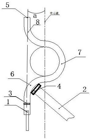
[0020] Such as figure 1 As shown, this specific embodiment provides a filling body self-rotating stirring device, including a cement slurry pipe 1, a rotating stirring pipe and a gangue conveying mechanism 2, and the rotating stirring pipe is provided with a cement slurry inlet 3, a gangue particle inlet and a mixing body outlet 5, the cement slurry pipe 1 is connected to the cement slurry inlet 3, and the feeding end 4 of the gangue conveying mechanism 2 is located at the gangue particle inlet; Vortex channel section 8, second stage reverse vortex channel section 7 and first stage forward vortex channel section 6, third stage forward vortex channel section 8, second stage reverse vortex channel section 7 and first stage forward The vortex channel sections 6 are all arc-shaped structures, and the curved orientation of the second-stage reverse vortex channel section 7 (that is, toward the left in the figure) is the same as that of the third-stage forward vortex channel section ...

specific Embodiment approach 2

[0023] This specific embodiment provides a filling body self-rotation stirring process, including the filling body self-rotation stirring device in the specific embodiment 1, and also includes the following steps:

[0024] A1: The mixture of cement and water flowing out of the cement slurry pipe 1 (referred to as cement slurry), enters the first-stage forward vortex channel section 6 through the cement slurry inlet 3, and connects with the feeding end 4 of the gangue conveying mechanism 2 The falling gangue particles are mixed, and the cement slurry and gangue particles are initially mixed through the rotation and tumbling of the clockwise cement slurry vortex in the second half of the first-stage vortex channel section 6;

[0025] A2: After preliminary mixing, pass through the second-stage reverse vortex channel section 7, and through the rotation and tumbling of the eddy current of the cement slurry in the counterclockwise direction, the cement slurry and gangue particles are...


PUM


Abstract

The invention provides a self-rotating stirring device for a filling body and a process thereof, and relates to the technical field of mine equipment, and the adopted scheme is that the self-rotating stirring device comprises a cement paste pipe, a rotating stirring pipe and a gangue conveying mechanism, the rotary stirring pipe comprises a third-stage forward vortex flow channel section, a second-stage reverse vortex flow channel section and a first-stage forward vortex flow channel section which are sequentially and continuously arranged from top to bottom and are all of an arc-shaped structure, and the cement slurry inlet and the gangue particle inlet are located in the first-stage forward vortex flow channel section. The gangue particle inlet is closer to the second-stage reverse vortex flow channel section relative to the cement slurry inlet, the mixture outlet is located in the third-stage forward vortex flow channel section, and a connecting line between the center of the cement slurry inlet and the center of the mixture outlet is obliquely arranged and forms an inclination angle a with the vertical direction. The problems that an existing paste pumping filling mode is high in investment and large in occupied area, and safety accidents are easily caused due to the fact that the pressure is high during long-distance conveying of a conveying pump are solved.

Description

technical field [0001] The invention relates to the technical field of mine equipment, in particular to a filling body self-rotating stirring device and a process thereof. Background technique [0002] In order to reduce the deformation of the ground surface after mining, it is usually necessary to carry out various filling methods on the mining roadway. Among them, the method with better effect, that is, the method that can form a better filling body is mainly pumping paste filling, pumping paste filling Special equipment such as cement silos, gangue silos, mixing stations, conveying pumps, etc. are required, and more equipment and sites will be used. After the above equipment and links are processed, a well-mixed filling body can be formed. [0003] It can be seen that the current pumping paste filling method has the problems of high investment and large occupied area, and when the pump is used for long-distance transportation, the pressure is high and there are potential ...

Claims


Application Information

Patent Timeline
Patent Type & Authority Applications(China)
IPC IPC(8): E21F15/08
CPCE21F15/08
Inventor 耿华锋
Owner XINWEN MINING GROUP
Why Eureka
Try Eureka