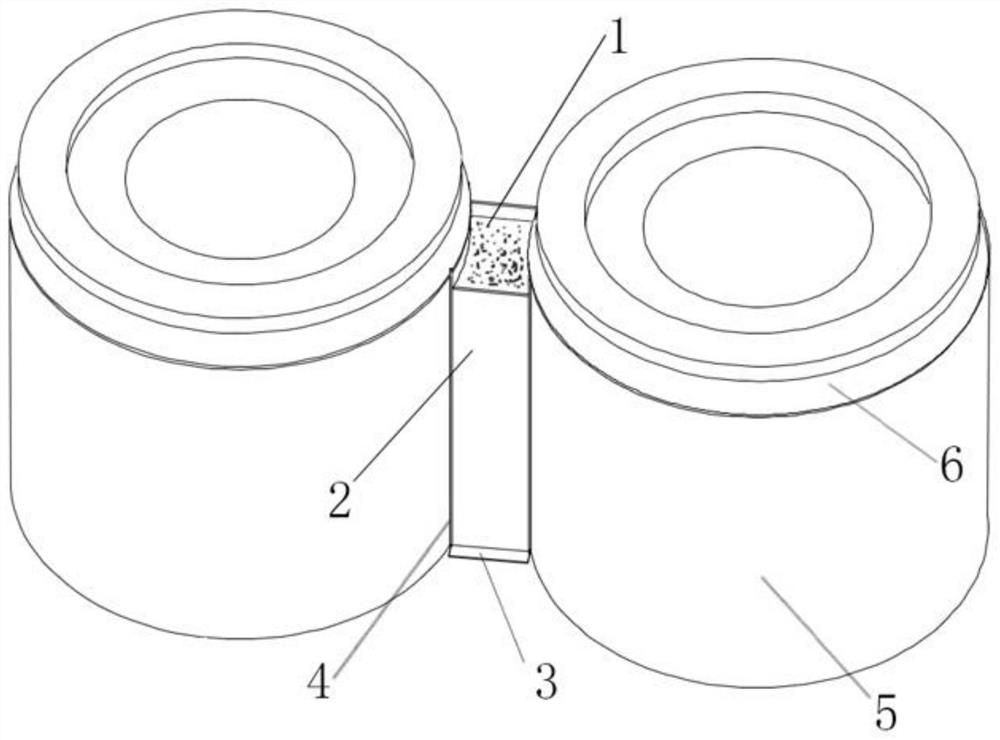
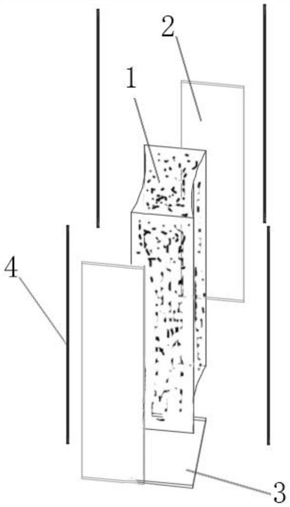
Filling process between dip pipes
A dipping tube and process technology, which is applied in the field of RH refining refractories and its preparation process, can solve the problems of high tank wall direction, inability to connect the dipping tube, and low center direction of the tank bottom, so as to ensure the production rhythm and avoid the inability to dock. , The effect of improving the utilization rate of refractory materials
- Summary
- Abstract
- Description
- Claims
- Application Information
AI Technical Summary
Problems solved by technology
Method used
Image

Examples
preparation example Construction
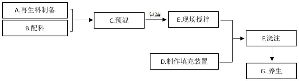
[0041] The preparation technology of refractory filling material 1 among the present invention is as follows:
[0042] A. Recycled material preparation: Put the used CAS cover castable into the jaw crusher for coarse crushing, and the crushed granular material is screened by a vibrating screen to obtain recycled material with a particle size of 5-20mm;
[0043] B. Ingredients: According to the proportioning relationship of each component raw material, configure plate-shaped corundum particles and fine powder, 76 fused spinel 325 mesh, α-alumina micropowder, pure calcium aluminate cement, 96 microsilica, water reducing agent, explosion-proof fiber, regenerated corundum spinel castable;
[0044] C. Pre-mixing: Put 5-20mm, 5-3mm, 3-1mm and 1-0.088mm particle size materials into the planetary mixer for 2-4min dry mixing, then add 240 mesh tabular corundum powder, 325 mesh 76 fused spinel powder, α-alumina micropowder, pure calcium aluminate cement, 96 microsilica fume, water redu...
Embodiment 1
[0051] A filling process between dipping tubes, the specific method is as follows:
[0052] A. Recycled material preparation: Put the used CAS cover castable into the jaw crusher for coarse crushing, and the crushed granular material is screened by a vibrating screen to obtain recycled material with a particle size of 5-20mm;
[0053] B. Ingredients: According to the proportioning relationship of each component raw material in Table 1, configure plate-shaped corundum particles and fine powder, 76 fused spinel 325 mesh, α-alumina micropowder, pure calcium aluminate cement, and 96 microsilica , water reducing agent, explosion-proof fiber, regenerated corundum spinel castable;
[0054] The composition raw material weight ratio of table 1 embodiment 1 refractory filler
[0055]
[0056] Among them, the platy corundum granules and subdivided composition are 5-3mm, accounting for 22%, 3-1mm accounting for 34%, 1-0.088mm accounting for 30%, 240 mesh accounting for 14%; the water ...
PUM
| Property | Measurement | Unit |
|---|---|---|
| diameter | aaaaa | aaaaa |
| density | aaaaa | aaaaa |
| compressive strength | aaaaa | aaaaa |
Abstract
Description
Claims
Application Information
 - R&D
- Intellectual Property
- Life Sciences
- Materials
- Tech Scout
- Unparalleled Data Quality
- Higher Quality Content
- 60% Fewer Hallucinations
Browse by: Latest US Patents, China's latest patents, Technical Efficacy Thesaurus, Application Domain, Technology Topic, Popular Technical Reports.
© 2025 PatSnap. All rights reserved.Legal|Privacy policy|Modern Slavery Act Transparency Statement|Sitemap|About US| Contact US: help@patsnap.com