
Emission device for emitting electrons, preparation method of emission device and electron gun

An emission device and a technology for emitting electrons, which are applied in the field of electron guns to achieve the effects of reducing thermal stress and thermal deformation, reducing manufacturing difficulty, and reducing sealing and assembly difficulty

Pending Publication Date: 2022-05-10
AEROSPACE INFORMATION RES INST CAS
View PDF0 Cites 0 Cited by
  • Summary
  • Abstract
  • Description
  • Claims
  • Application Information

AI Technical Summary

Problems solved by technology

[0004] But as far as the existing electron gun is concerned, with the increase of operating frequency, the electron gun for traveling wave tube is very sensitive to the parameter changes of cathode, anode and focusing electrode, which puts forward very high requirements for the processing and assembly of electron gun

Method used


Image

  • Emission device for emitting electrons, preparation method of emission device and electron gun
  • Emission device for emitting electrons, preparation method of emission device and electron gun
  • Emission device for emitting electrons, preparation method of emission device and electron gun

Examples


Embodiment Construction

[0112] In order to make the object, technical solution and advantages of the present invention clearer, the present invention will be further described in detail below in conjunction with specific embodiments and with reference to the accompanying drawings.

[0113] The terminology used herein is for the purpose of describing particular embodiments only, and is not intended to be limiting of the invention. The terms "comprising", "comprising", etc. used herein indicate the presence of stated features, steps, operations and / or components, but do not exclude the presence or addition of one or more other features, steps, operations or components.

[0114] All terms (including technical and scientific terms) used herein have the meaning commonly understood by one of ordinary skill in the art, unless otherwise defined. It should be noted that the terms used herein should be interpreted to have a meaning consistent with the context of this specification, and not be interpreted in an...


PUM


Abstract

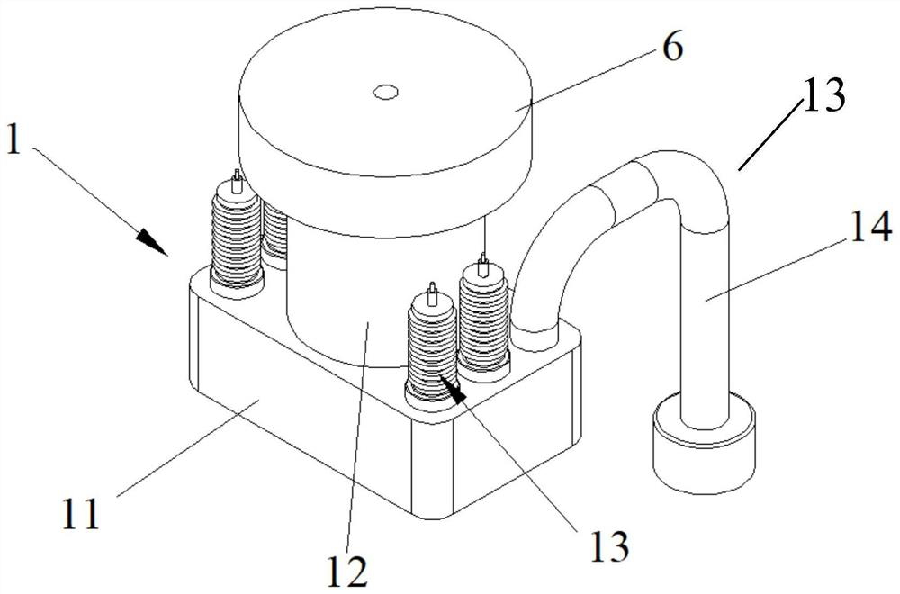
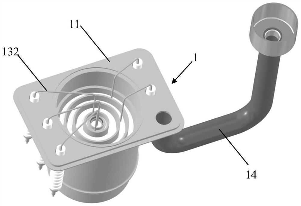
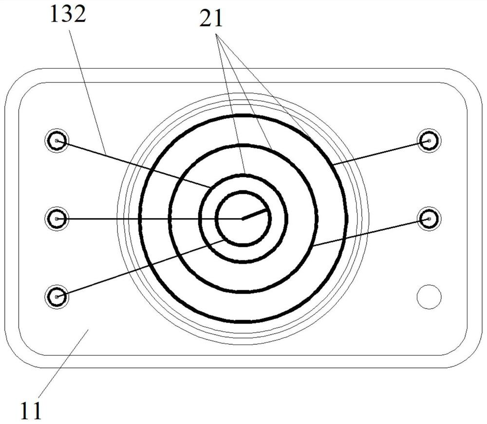
The invention discloses an emission device for emitting electrons, a preparation method thereof and an electron gun. An emission device used for emitting electrons comprises a main body part, at least four conductive electrode positioning rings, a first electrode positioning ring, a second electrode positioning ring, a third electrode positioning ring, a fourth electrode positioning ring and a fourth electrode positioning ring, the electrode positioning ring comprises a center positioning ring located in the center, an outer side positioning ring located on the outermost side and a plurality of middle positioning rings located between the center positioning ring and the outer side positioning ring. The at least three ceramic rings are respectively arranged between two adjacent electrode positioning rings; the cathode heat shield assembly is mounted in the central positioning ring; the control electrode is arranged on the central positioning ring; the at least one anode is arranged on the middle positioning ring; and the end cover is combined on the outer side positioning ring, and the control electrode and the anode extend into a containing groove, facing the main body part, of the end cover.

Description

technical field [0001] At least one embodiment of the present invention relates to an electron gun, especially an emission device for emitting electrons, a manufacturing method thereof, and an electron gun. Background technique [0002] With the continuous development of vacuum electronic technology, the requirements for the performance of traveling wave tubes in military electronics industry and civilian industry are also getting higher and higher. As a high-power broadband microwave source and an important microwave signal amplifier, traveling wave tubes have an irreplaceable position in related industries. The development of modern satellite communication, space communication, phased array radar and other technologies has put forward higher requirements for traveling wave tubes in terms of high frequency band, long life and high reliability. [0003] At present, the difficulty of the manufacturing process has become the core problem that limits the application of devices...

Claims


Application Information

Patent Timeline
IPC IPC(8): H01J23/06H01J23/12H01J9/18H01J25/34
CPCH01J23/06H01J23/12H01J9/18H01J25/34
Inventor 王建
Owner AEROSPACE INFORMATION RES INST CAS
Learn More