Apparatus and method for inhibiting growth of oxidation film on coiled stock
A technology for inhibiting oxidation and coiling, applied in metal rolling, manufacturing tools, metal rolling, etc., can solve the problems of increasing the cost of pickling, reducing the conveying speed of rolled strips, and reducing productivity.
- Summary
- Abstract
- Description
- Claims
- Application Information
AI Technical Summary
Problems solved by technology
Method used
Image
Examples
no. 1 example
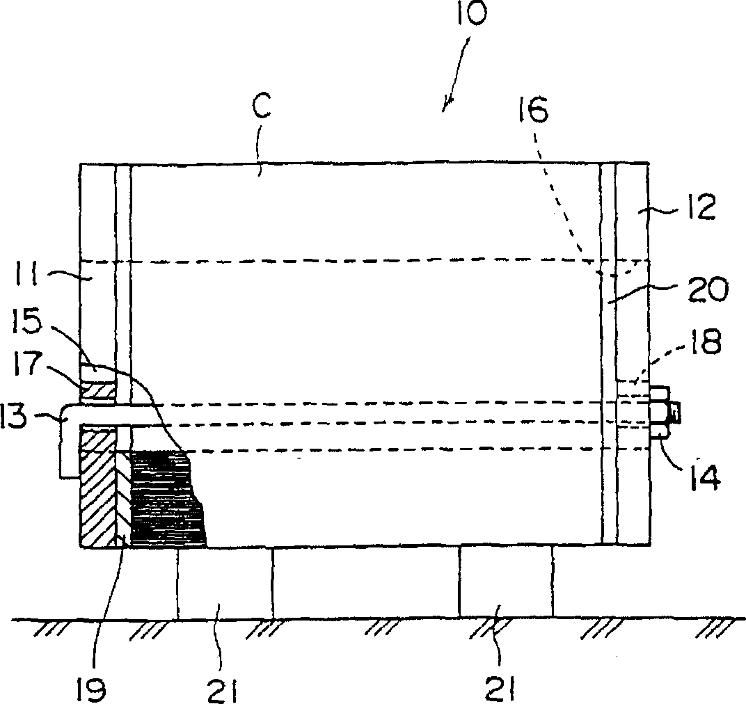
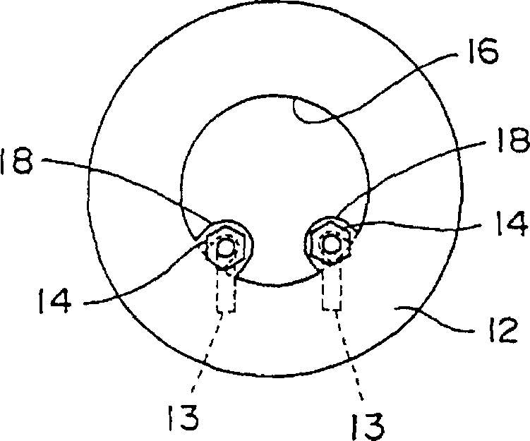
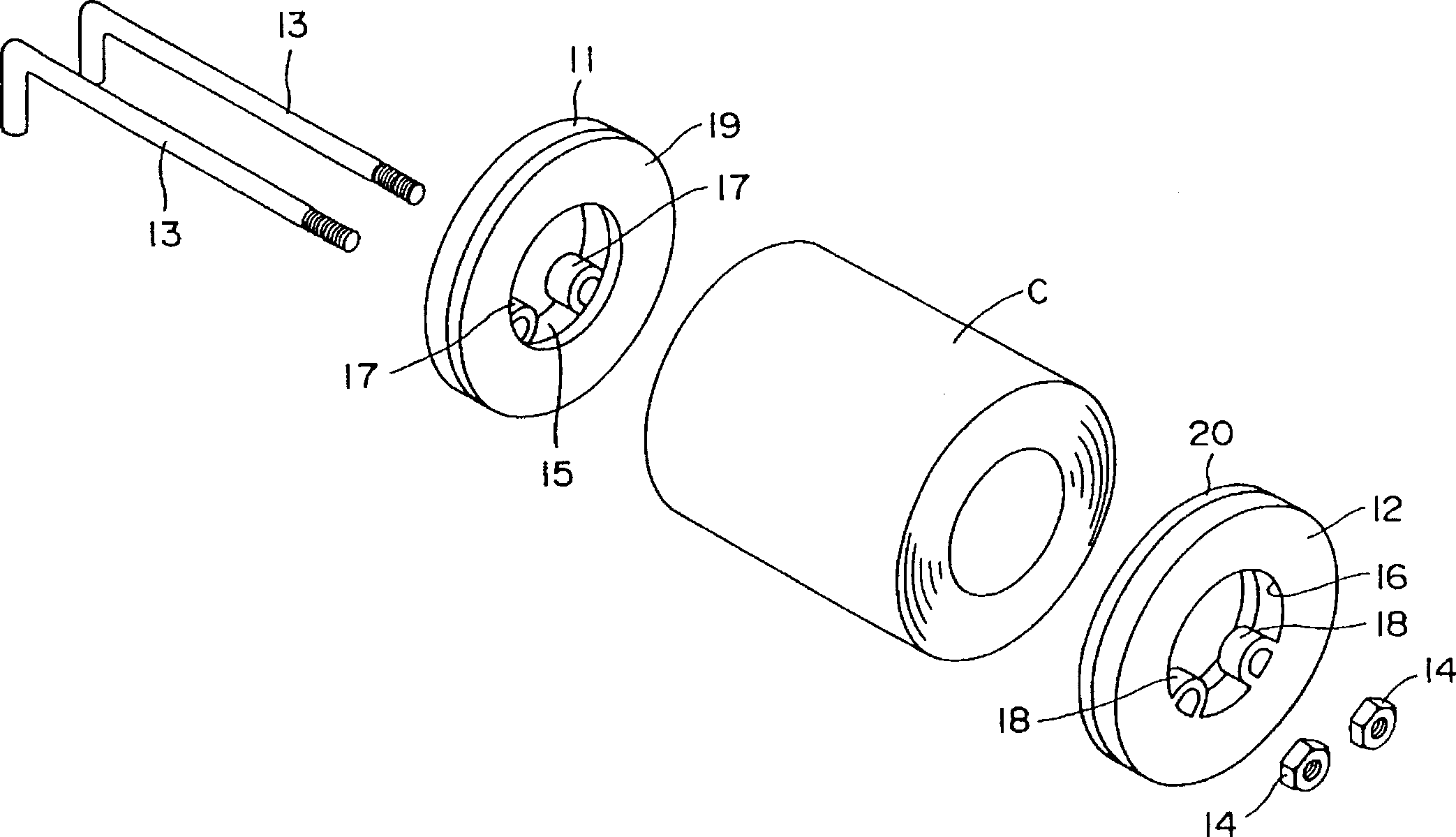
[0041] 1 is a partially cutaway front view of an apparatus for suppressing the growth of an oxide film on a coil according to a first embodiment of the present invention. method of growth. figure 2 is a side view of a device for suppressing the growth of an oxide film on a coil. image 3 is an exploded perspective view of a device for suppressing the growth of an oxide film on a coil. Figure 4 is a graph showing the oxide film thickness in the coil width direction in the apparatus for suppressing the growth of an oxide film on a coil according to the present embodiment.
[0042] As shown in Figures 1-3, a coil C is rolled by a hot rolling facility (not shown) and then helically wound by a down coiler. The formed coil is sent to a coil yard where it is stored by means of an apparatus 10 for suppressing the growth of an oxide film on a coil according to this embodiment. The device 10 includes a pair of covers (left and right covers) 11, 12 for covering opposite sides of the...
no. 2 example
[0048] 5 is a partially cutaway front view of an apparatus for suppressing growth of an oxide film on a coil according to a second embodiment of the present invention. Image 6 is a side view of a device for suppressing the growth of an oxide film on a coil. Figure 7 is a graph showing the oxide film thickness in the coil width direction in the apparatus for suppressing the growth of an oxide film on a coil according to the present embodiment. Figure 8 is a graph showing the relationship between coil temperature and coil cooling time. Components having the same functions as those shown in the above-described embodiments are denoted by the same reference numerals, and descriptions thereof are omitted.
[0049] As shown in FIGS. 5 and 6, an apparatus 30 for suppressing the growth of an oxide film on a coil has a pair of covers (left and right covers) 31, 32, which are mounted on a coil C so that Cover both opposite sides of the tape roll. In each cover 31, 32, a cooling wat...
no. 3 example
[0056] 9 is a partially cutaway front view of an apparatus for suppressing growth of an oxide film on a coil according to a third embodiment of the present invention. Figure 10 is a side view of a device for suppressing the growth of an oxide film on a coil.
[0057]As shown in FIGS. 9 and 10, a device 50 for suppressing the growth of an oxide film on a coil includes a cup-shaped member 51 (cover plate) for accommodating a coil C so as to cover one side portion of the coil C and A cover member 52 is attached to the cup member 51 so as to cover the other side portion of the coil C. As shown in FIG. The cup member 51 is made of steel and has a cylindrical shape having an inner peripheral portion having a diameter slightly larger than that of the coil C. As shown in FIG. The cover member 52 is also made of steel and has a cylindrical shape having an inner peripheral portion which fits on the outer peripheral portion of the cup member 51 . The coil C is loaded onto the cup 51 w...
PUM
| Property | Measurement | Unit |
|---|---|---|
| thickness | aaaaa | aaaaa |
| thickness | aaaaa | aaaaa |
Abstract
Description
Claims
Application Information
 - R&D
- Intellectual Property
- Life Sciences
- Materials
- Tech Scout
- Unparalleled Data Quality
- Higher Quality Content
- 60% Fewer Hallucinations
Browse by: Latest US Patents, China's latest patents, Technical Efficacy Thesaurus, Application Domain, Technology Topic, Popular Technical Reports.
© 2025 PatSnap. All rights reserved.Legal|Privacy policy|Modern Slavery Act Transparency Statement|Sitemap|About US| Contact US: help@patsnap.com


