Gas waste heat recovery and purification device and system thereof

A waste heat recovery and purification device technology, applied in preheating, steam condensation, lighting and heating equipment, etc., can solve problems such as energy waste, low steam utilization rate, and affecting the normal production process

Pending Publication Date: 2022-05-10
FOSHAN KINGXUNENG COLD CHAIN TECH CO LTD
View PDF0 Cites 0 Cited by
  • Summary
  • Abstract
  • Description
  • Claims
  • Application Information

AI Technical Summary

Problems solved by technology

[0002] In the process of energy consumption, generally only a part of the energy can be rationally utilized, and the other part of the energy is turned into waste heat and waste energy in different forms. If the waste heat is discharged directly, it will lead to waste of energy and damage to the environment.
[0003] Specifically, the molding of EPP (polypropylene plastic foam material) and EPS (polystyrene foam) in the packaging industry requires a large amount of steam, but due to the limitation of the process, the utilization rate of these steams is not high and produces a lot of exhaust gas. Contains a large amount of latent heat of condensation, if it is directly discharged, it will lead to a waste of energy; and the exhaust gas inevitably contains a lot of non-condensable gas, if the exhaust gas is recovered by traditional vapor compression and recovery, and the recovered exhaust gas The gas is directly applied to the production process, and the non-condensable gas contained in the exhaust gas will affect the normal production process

Method used


Image

  • Gas waste heat recovery and purification device and system thereof
  • Gas waste heat recovery and purification device and system thereof
  • Gas waste heat recovery and purification device and system thereof

Examples


Embodiment 1

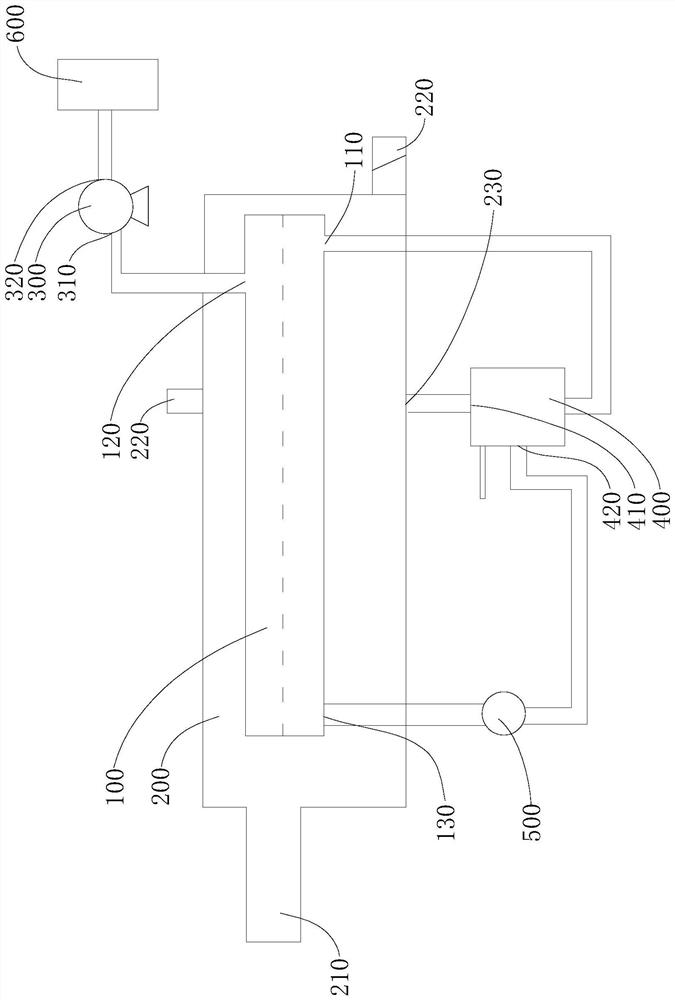
[0037] Embodiment one, see figure 1 , The embodiment of the present invention provides a gas waste heat recovery and purification device, including: an evaporation chamber 100 , a condensation chamber 200 , an air extraction device 300 and a condensed water collector 400 .

[0038] Among them, the condensation chamber 200 is provided with a first air inlet 210, a second air outlet 220 and a first water outlet 230, and EPP (polypropylene plastic foam material) and EPS (polystyrene foam) in the packaging industry are foamed The molding equipment will generate more exhaust air, and the exhaust air itself has a certain temperature, and the exhaust air can pass into the condensation chamber 200 from the first air inlet 210 .

[0039] The evaporation chamber 100 is provided with a first water inlet 110 and a first exhaust port 120, and the air extraction device 300 communicates with the first exhaust port 120, and the air extraction device 300 can perform air extraction on the evapo...

Embodiment 2

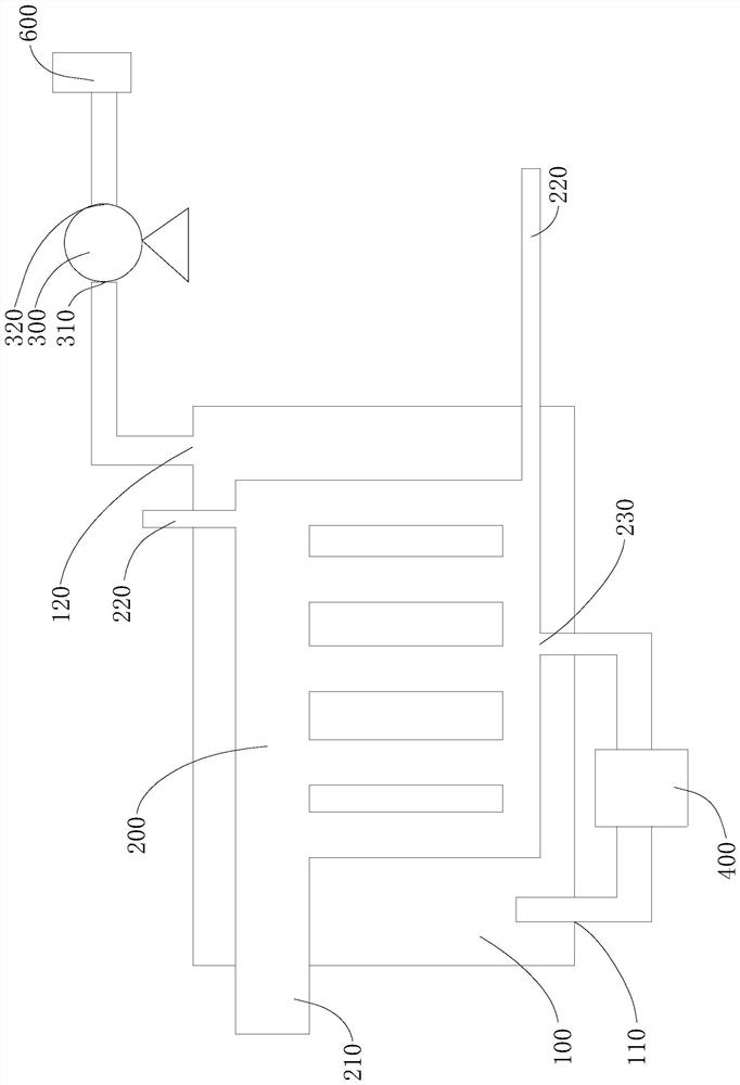
[0074] Embodiment two, see figure 2 , the embodiment of the present invention also provides a gas waste heat recovery and purification device, including: an evaporation chamber 100, a condensation chamber 200, an air extraction device 300 and a condensed water collector 400, wherein the structures of the evaporation chamber 100 and the condensation chamber 200 are the same as The first embodiment is roughly the same, the main difference is that the evaporation chamber 100 can be arranged around the outside of the condensation chamber 200, which is beneficial to increase the connecting area between the condensation chamber 200 and the evaporation chamber 100, that is, to increase the heat exchange area between the two, and also to It is beneficial to realize the comprehensive heat exchange between the condensation chamber 200 and the evaporation chamber 100. The junction of the condensation chamber 200 and the evaporation chamber 100 shares the same wall surface, that is, the m...

Embodiment 3

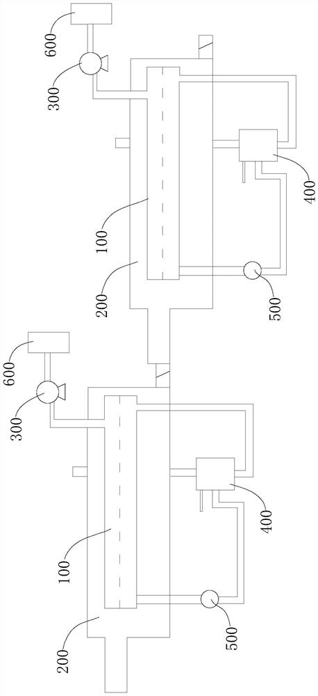
[0076] Embodiment three, see image 3 , the embodiment of the present invention also provides a exhaust gas waste heat recovery and purification system, including: a plurality of gas waste heat recovery and purification devices as provided in Embodiment 1 or Embodiment 2, and a plurality of gas waste heat recovery and purification devices are arranged in an array And connected in sequence.

[0077] In order to further recover the waste heat of exhaust gas, the waste heat recovery and purification system of exhaust gas is equipped with multiple gas waste heat recovery and purification devices, which are connected in sequence through multiple gas waste heat recovery and purification devices, so as to realize the function of waste heat recovery of exhaust gas step by step .

[0078] In the exhaust gas waste heat recovery and purification system, the pressure in the evaporation chamber 100 of the gas waste heat recovery and purification device located at the rear and the boiling ...


PUM

PropertyMeasurementUnit
thermal conductivityaaaaaaaaaa

Abstract

The invention discloses a gas waste heat recovery and purification device and system, and the device comprises an evaporation chamber which is provided with a first water inlet and a first exhaust port; the condensation chamber is connected with the evaporation chamber, and the condensation chamber is provided with a first air inlet, a second air outlet and a first water outlet; the air extracting device is communicated with the first exhaust port, and the air extracting device can be used for extracting air from the evaporation chamber; and the condensate water collector is respectively communicated with the first water outlet and the first water inlet, and the condensate water collector is used for collecting condensate water condensed in the condensation chamber and supplying the condensate water into the evaporation chamber. The boiling point of water in the evaporation chamber is lower than the continuous condensation point of the condensation chamber, waste heat recovery of exhaust gas is achieved, pure condensate water is generated in the condensation heat release process of the exhaust gas, and therefore separation of non-condensable gas in the exhaust gas is achieved.

Description

technical field [0001] The invention relates to the technical field of gas waste heat recovery and purification, in particular to a gas waste heat recovery and purification device and system thereof. Background technique [0002] In the process of energy consumption, generally only a part of the energy can be rationally utilized, and the other part of the energy is turned into waste heat and waste energy in different forms. If the waste heat is discharged directly, it will lead to waste of energy and damage to the environment. [0003] Specifically, the molding of EPP (polypropylene plastic foam material) and EPS (polystyrene foam) in the packaging industry requires a large amount of steam, but due to the limitation of the process, the utilization rate of these steam is not high and produces a lot of exhaust gas, exhaust air Contains a large amount of latent heat of condensation, if it is directly discharged, it will lead to a waste of energy; and the exhaust gas inevitably ...

Claims


Application Information

Patent Timeline
Patent Type & Authority Applications(China)
IPC IPC(8): F22B1/16F22B3/04F22D11/06B01D5/00
CPCF22B1/16F22B3/04F22D11/06B01D5/006B01D5/0075B01D5/009B01D5/0093
Inventor 黄国平周明军周建杰
Owner FOSHAN KINGXUNENG COLD CHAIN TECH CO LTD
Why Eureka
Try Eureka