
Vertical grounding structure with anchor disc and construction method thereof

A technology of vertical grounding and construction method, applied in infrastructure engineering, connection, connection contact material, etc., can solve the problems of inability to use post-grouting technology for transmission lines, low feasibility of site foundation treatment, and poor economic benefits, etc. Good grouting effect, preventing orifice blockage and reducing the amount of foundation works

Pending Publication Date: 2022-05-06
POWERCHINA FUJIAN ELECTRIC POWER SURVEY & DESIGN INST CO LTD +2
View PDF0 Cites 0 Cited by
  • Summary
  • Abstract
  • Description
  • Claims
  • Application Information

AI Technical Summary

Problems solved by technology

[0004] (1) The foundation construction of transmission lines has its particularity. It is different from conventional industrial and civil buildings. The number of foundations on the construction site is small, the feasibility of carrying out large-scale site foundation treatment is low, and the economic benefits are poor
[0005] (2) Post-grouting will often cause pipe plugging. In other buildings, the bearing capacity can be supplemented by adding piles on the side. However, there is only one foundation for each tower leg of the transmission line. If the post-grouting hole is blocked , may result in the scrapping of the foundation
[0006] Based on the above shortcomings, this patent proposes a post-grouting grounding method and construction method combined with the transmission line grounding method, which can further reduce the grounding resistance and improve the reliability of the line operation while solving the problem that the transmission line cannot use the post-grouting process sex

Method used


Image

  • Vertical grounding structure with anchor disc and construction method thereof
  • Vertical grounding structure with anchor disc and construction method thereof
  • Vertical grounding structure with anchor disc and construction method thereof

Examples


Embodiment Construction

[0041] The technical solutions in the embodiments of the invention will be clearly and completely described below in conjunction with the accompanying drawings in the embodiments of the invention. Obviously, the described embodiments are only part of the embodiments of the invention, not all of them. Based on the embodiments of the invention, all other embodiments obtained by persons of ordinary skill in the art without making creative efforts belong to the protection scope of the invention.

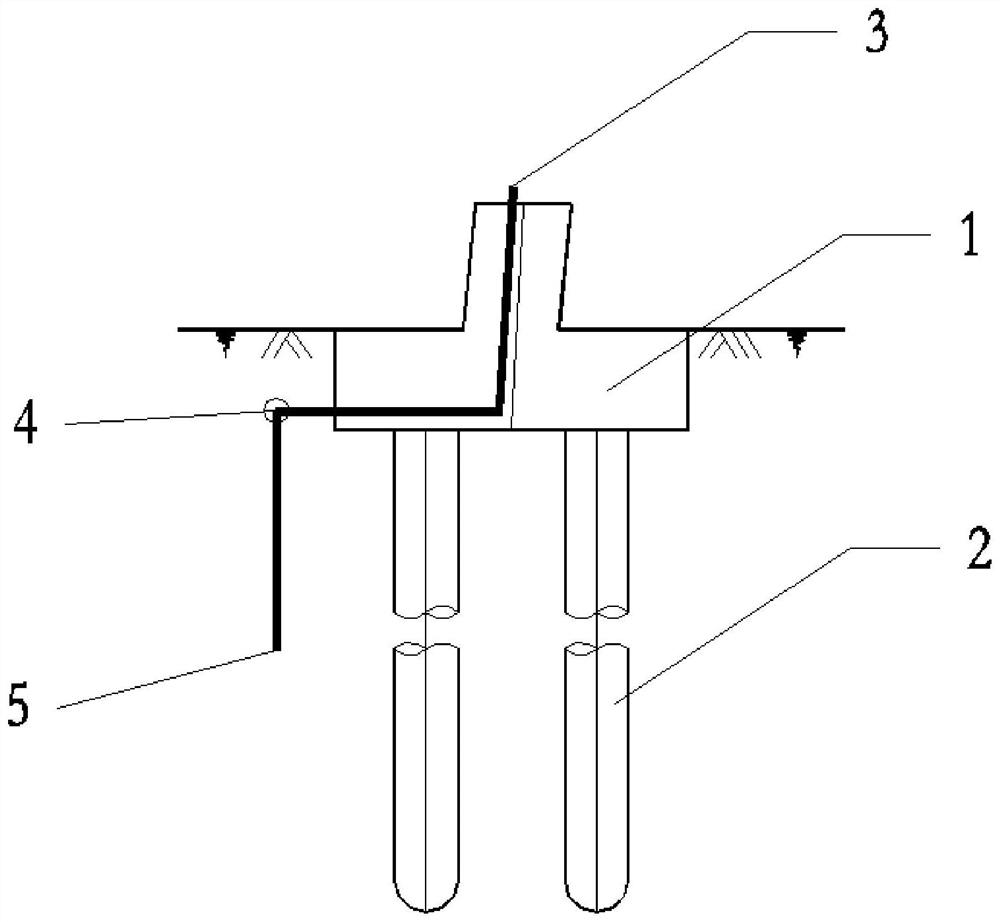
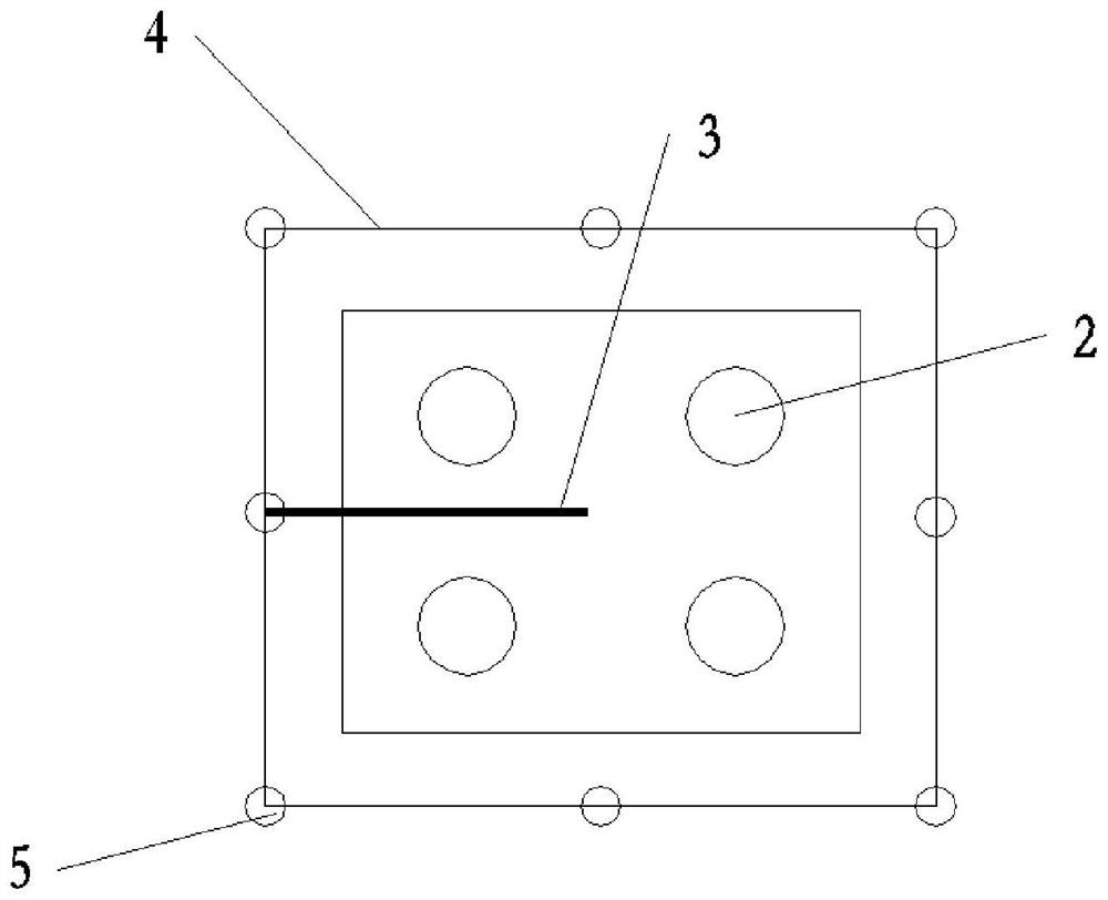
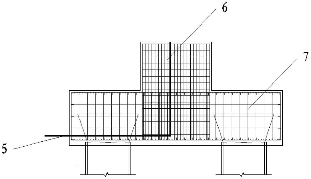
[0042] see Figure 1-2 , the invention provides a technical solution: a vertical grounding structure with an anchor plate, including a pile foundation cap 1, a number of pile foundations 2 connected to the bottom of the pile foundation cap 1, and a square grounding ring is arranged around the pile foundation cap 1 4. The grounding down-conductor 3 is connected to the square grounding ring 4, and the upper end of the grounding down-conductor 3 penetrates through the inside of the pile fou...


PUM


Abstract

The invention discloses a vertical grounding structure with an anchor disc and a construction method of the vertical grounding structure in the technical field of power transmission network grounding, the structure is constructed in a screwing mode, grouting holes are formed around the anchor disc, and grout can be diffused outwards through the grouting holes, so that the contact area between a grouting opening and a soil layer is large, the grouting effect is good, and the construction efficiency is improved. According to the construction method, grouting holes do not need to be formed in the pile foundation, scrapping of other foundations of a power transmission line caused by grouting hole blocking can be effectively avoided, post grouting of the pile foundation is carried out through novel vertical grounding, and therefore even if the hole blocking phenomenon occurs in post grouting, the vertical grounding hole position can be supplemented, and the post grouting quality can be guaranteed.

Description

technical field [0001] The invention relates to the technical field of transmission network grounding, in particular to a vertical grounding structure with an anchor plate and a construction method thereof. Background technique [0002] Cast-in-situ pile foundations are widely used in transmission lines in flat areas. Post-grouting technology to improve the bearing capacity of pile foundations is a relatively mature treatment method for pile foundations. This technology has been widely used in other industrial and civil buildings, and in "Technical Specifications for Building Pile Foundations" (JGJ94-2008) has stipulated the lifting calculation method for the calculation of the down-pressure bearing capacity. [0003] Post-grouting foundations have not been used in transmission lines for two main reasons: [0004] (1) The foundation construction of transmission lines has its particularity. It is different from conventional industrial and civil buildings. The number of foun...

Claims


Application Information

Patent Timeline
Patent Type & Authority Applications(China)
IPC IPC(8): H01R4/66H01R43/00E02D27/14E02D15/02E02D5/80E02D3/12
CPCH01R4/66H01R43/00E02D27/14E02D15/02E02D3/12E02D5/80
Inventor 张文翔齐悦王传杰崔峥危剑锋郭江南杨卓帅许贤贵傅林林锐
Owner POWERCHINA FUJIAN ELECTRIC POWER SURVEY & DESIGN INST CO LTD
Learn More