In-situ test equipment for laser thermal shock test of accelerated life of coating

An accelerated life and in-situ testing technology, applied in the direction of measuring devices, instruments, scientific instruments, etc., can solve the problem that the real-time observation and recording of sample coating cracks cannot be performed, and the thermal shock equipment cannot accurately obtain the surface temperature of the heated sample coating And other issues

Active Publication Date: 2022-05-06
ZHENGZHOU UNIVERSITY OF LIGHT INDUSTRY
View PDF8 Cites 2 Cited by
  • Summary
  • Abstract
  • Description
  • Claims
  • Application Information

AI Technical Summary

Problems solved by technology

[0010] An in-situ test equipment for accelerated life laser thermal shock test, including a laser generator and a control system, a cooling system, a temperature measurement system, an in-situ observation system, a clamp system and a control module; the laser generator and the control system solve the problem of adopting All the shortcomings brought about by flame heating have achieved the effect of rapid and precise temperature rise on the sample coating. Its components include: pump source, glass optical fiber, resonant cavity, collimating optical system, flat-top light shaper, The casing part, the power control cabinet; the cooling process of the reduced coating sample in the cooling system, and its components include: air compressor, universal wheel with self-locking function, air storage tank, air hose, flow control valve, Triangular bracket; the temperature measurement system solves the problem that all current thermal shock equipment cannot accurately obtain the surface temperature of the heated sample coating. Its components include: infrared thermometer, adjustable thermometer bracket, temperature sensor, computer, tube card, coating absorption rate test device (such as Figure five ), computer cabinet; the in-situ observation system solves the problem that the test equipment cannot observe and record the cracks of the sample coating in real time during the heating process. Its components include: No. 1 CCD camera, No. 2 CCD camera, and No. 3 CCD Camera, No. 4 CCD camera, UV filter, zoom lens, computer, tripod bracket, camera adjustable fixture, direction adjustable LED light, computer cabinet, motor support column, adjustable bracket, data cable; machine clamp system to solve thermal shock The problem of experimental efficiency is that its components include: aluminum alloy rotating cross shaft, stepper motor, sample fixture, and motor support column; the control module of the present invention not only makes up for the defect that the coating absorption rate cannot be detected in real time, but also fills in the current experimental problems. There is a lack of accelerated life test methods and life prediction functions in the equipment. Its components include: coating absorption rate test module, image digitization and processing module and accelerated life test module

Method used


Image

  • In-situ test equipment for laser thermal shock test of accelerated life of coating
  • In-situ test equipment for laser thermal shock test of accelerated life of coating
  • In-situ test equipment for laser thermal shock test of accelerated life of coating

Examples


Embodiment 1

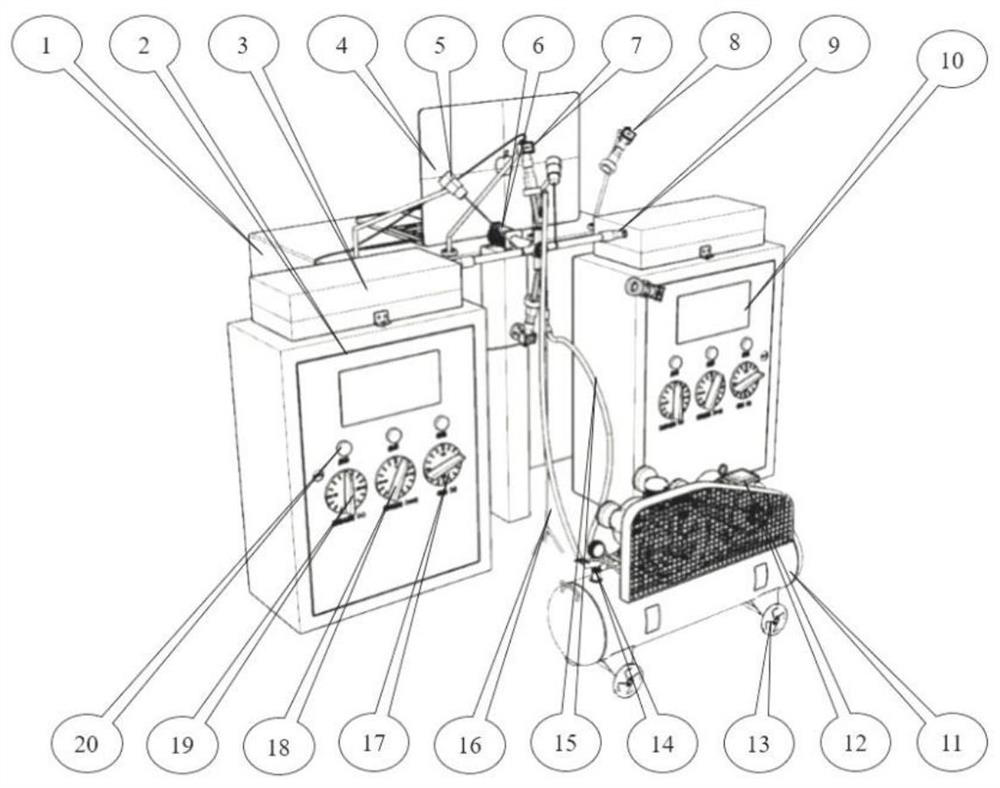
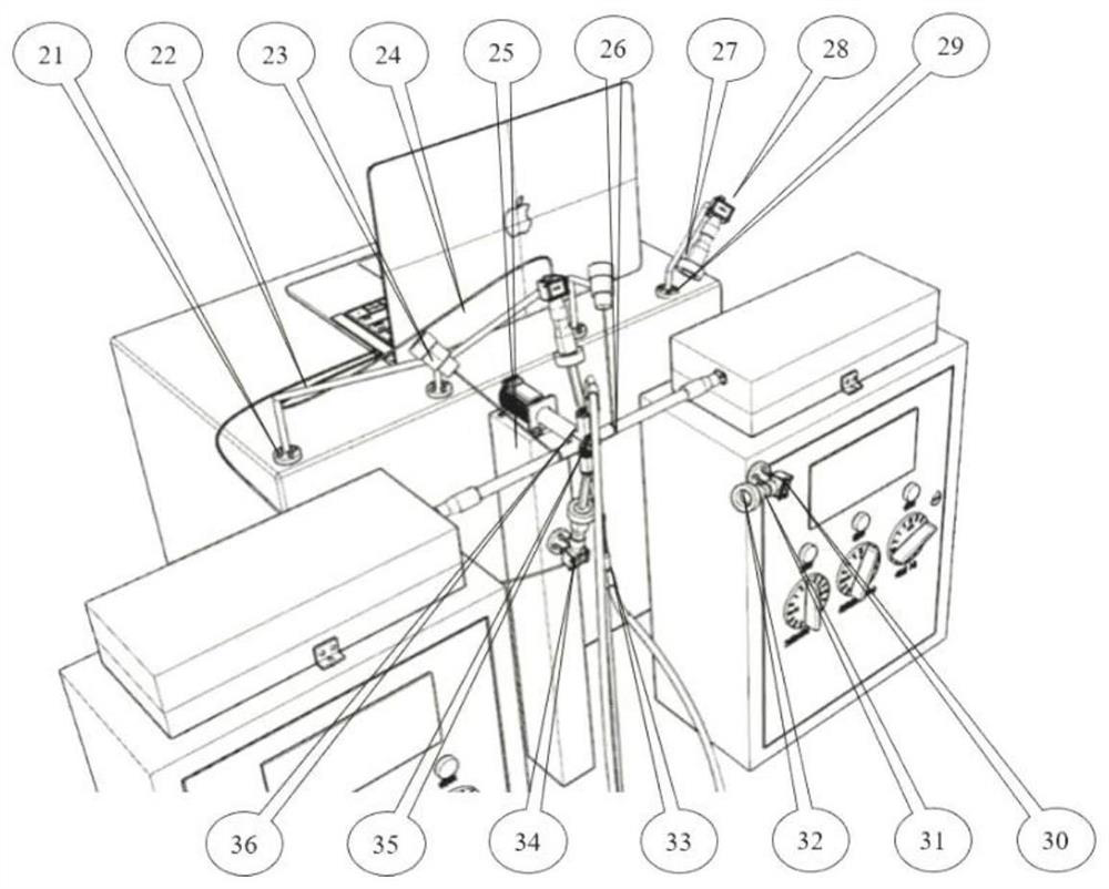
[0035] Such as figure 1 , 2 As shown, an in-situ test equipment for accelerated life laser thermal shock test of the present invention includes a laser generator and a control system, a cooling system, a temperature measurement system, an in-situ observation system, a machine clamp system and a control module. Among them, the laser generator and control system solve all the shortcomings caused by flame heating, and achieve the effect of rapid and precise temperature rise on the sample coating. Its components include: pump source, glass optical fiber, resonant cavity, quasi- Straight optical system, flat-top light shaper 9, casing part 3, power control cabinet 2. The cooling system realizes the function of fully reducing the service condition of the sample coating, and its components include: an air compressor 12, a universal wheel 13 with a self-locking function, an air storage tank 11, an air hose 15, a flow rate Control valve 14, position-adjustable chuck, and triangular ...

Embodiment 2

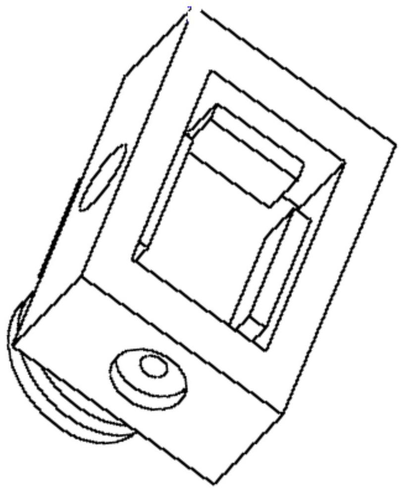
[0047] Such as image 3 As shown, the square sample holder of the present invention is disclosed, which is composed of three parts: a quadrangular clamp body, a clamping bolt (×4), and a rectangular pressing plate (×4); as Figure 4 As shown, it is a circular workpiece fixture, which consists of three parts: a cylindrical clamp body, a clamping bolt (×3), and an arc-shaped pressure plate (×3). A detachable connection is formed between the external thread of the bottom protruding part of the two sets of clamping devices and the internal thread of the rotating cross shaft.

[0048] The advantage of the above-mentioned device: since the sample holder and the rotating cross shaft are detachably connected, the experimental device has diversity in the selection of samples.

[0049] After adopting the square sample fixture, the test steps are as follows:

[0050] Step 1: Select the appropriate sample fixture according to the shape and size of the sample to be tested, adjust the tig...


PUM


Abstract

The invention discloses accelerated life laser thermal shock in-situ test equipment which comprises a laser generator, a control system, a cooling system, a temperature measurement system, an in-situ observation system, a sample clamp and the like, by combining the advantages of three fields of a high-temperature thermal shock performance testing technology, an in-situ observation technology of coating cracks, coating stripping and failure processes and an accelerated life testing technology of additive manufacturing coatings, crack initiation, expansion, competitive growth, failure modes and failure processes of various coatings in a high-temperature environment can be reduced; and predicting the high-temperature thermal shock life of the coating. The fiber laser generator is used as a heat source, and the heat source is stable in power, easy to quantify, fast in temperature rise and large in temperature rise range; the in-situ observation system can be used for observing and recording the initiation and propagation of cracks on the section of the coating, the peeling of the coating and the failure process and mode of the coating in real time; the accelerated life test can predict the service life of the coating at different temperatures, and is beneficial to establishing life prediction models at different temperatures.

Description

technical field [0001] The patent of the present invention combines the advantages of the three fields of high-temperature thermal shock performance testing technology of additive manufacturing coatings, in-situ observation technology of coating cracks and failure modes, and accelerated life testing technology, and relates to a high-temperature thermal shock performance of coatings. In-situ testing equipment, in particular to an in-situ testing equipment for accelerated life laser thermal shock. Background technique [0002] The purpose of the coating thermal shock test is to measure the ability of the coating prepared by additive manufacturing technology to resist the internal thermal stress concentration caused by the surface and interface crack growth, surface cracking, wrinkle removal and peeling off under the action of heating-cooling cycle. [0003] After studying the existing patents or literature, it is found that the most widely used test method is to use a flame sp...

Claims


Application Information

Patent Timeline
Patent Type & Authority Applications(China)
IPC IPC(8): G01N3/60G01N3/06
CPCG01N3/60G01N3/068G01N2203/0226G01N2203/0641Y02E30/30
Inventor 刘琨杜康平郭星明五一马军何文斌
Owner ZHENGZHOU UNIVERSITY OF LIGHT INDUSTRY
Why Eureka
Try Eureka