
Cutter adjusting device

A technology of adjusting device and cutting knife, which is applied in the direction of welding/welding/cutting objects, manufacturing tools, non-electric welding equipment, etc., which can solve the problems of cumbersome operation and uncontrollable cutting length of aluminum wire

Pending Publication Date: 2022-05-06
深圳市泰达智能装备有限公司
View PDF0 Cites 1 Cited by
  • Summary
  • Abstract
  • Description
  • Claims
  • Application Information

AI Technical Summary

Problems solved by technology

[0005] Based on this, it is necessary to provide a cutting knife adjustment device for the uncontrollable cutting length of the aluminum wire and the cumbersome operation, especially when it is necessary to fine-tune the distance between the riving knife and the cutting knife.

Method used


Image

  • Cutter adjusting device
  • Cutter adjusting device
  • Cutter adjusting device

Examples


Embodiment Construction

[0050] In order to make the above objects, features and advantages of the present invention more comprehensible, specific implementations of the present invention will be described in detail below in conjunction with the accompanying drawings. In the following description, numerous specific details are set forth in order to provide a thorough understanding of the present invention. However, the present invention can be implemented in many other ways different from those described here, and those skilled in the art can make similar improvements without departing from the connotation of the present invention, so the present invention is not limited by the specific embodiments disclosed below.

[0051] In describing the present invention, it should be understood that the terms "center", "longitudinal", "transverse", "length", "width", "thickness", "upper", "lower", "front", " Back", "Left", "Right", "Vertical", "Horizontal", "Top", "Bottom", "Inner", "Outer", "Clockwise", "Counte...


PUM


Abstract

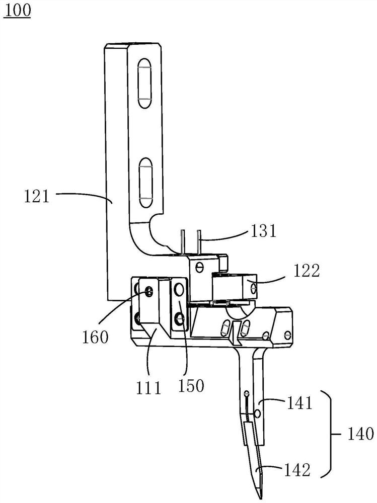
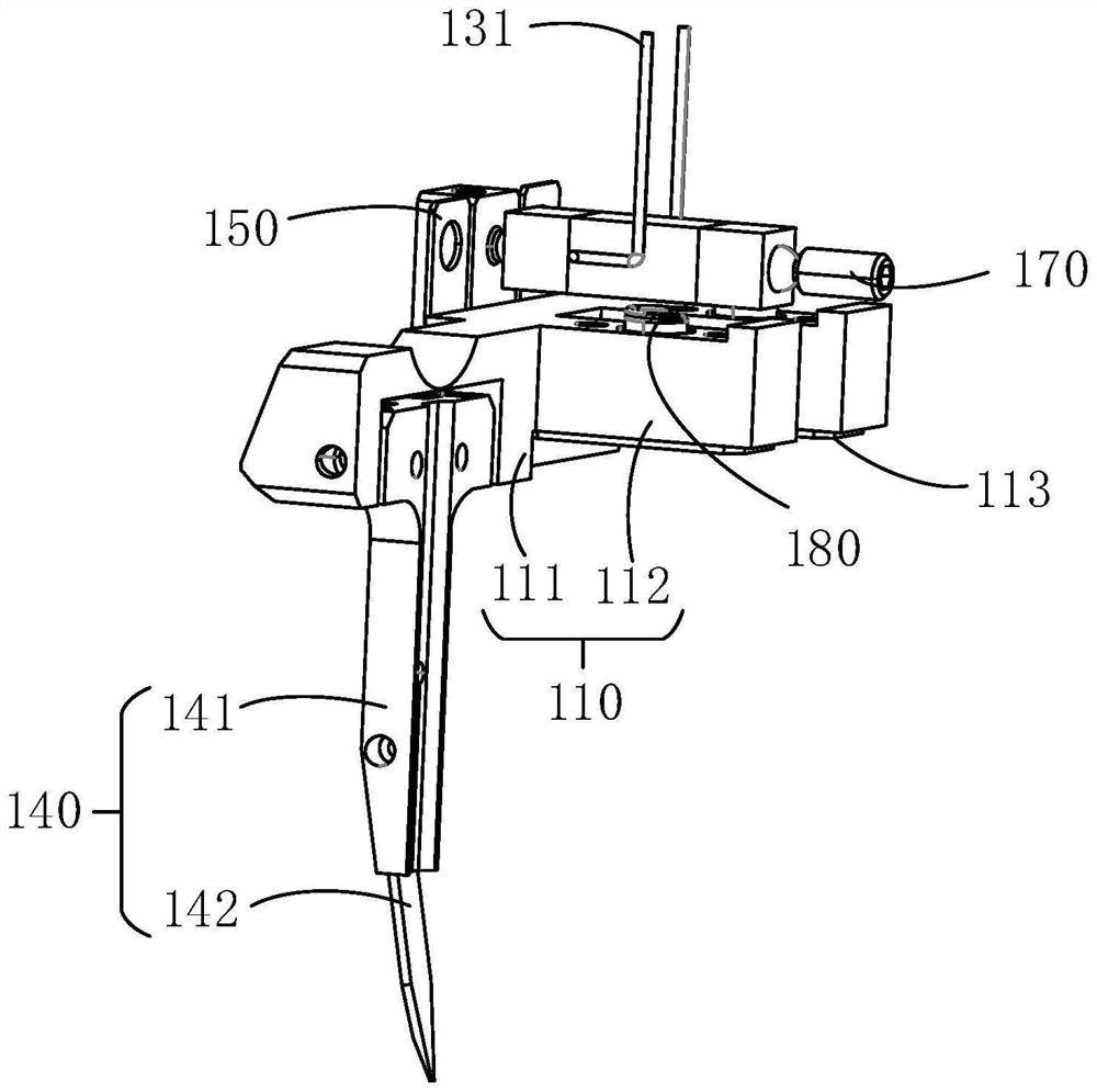
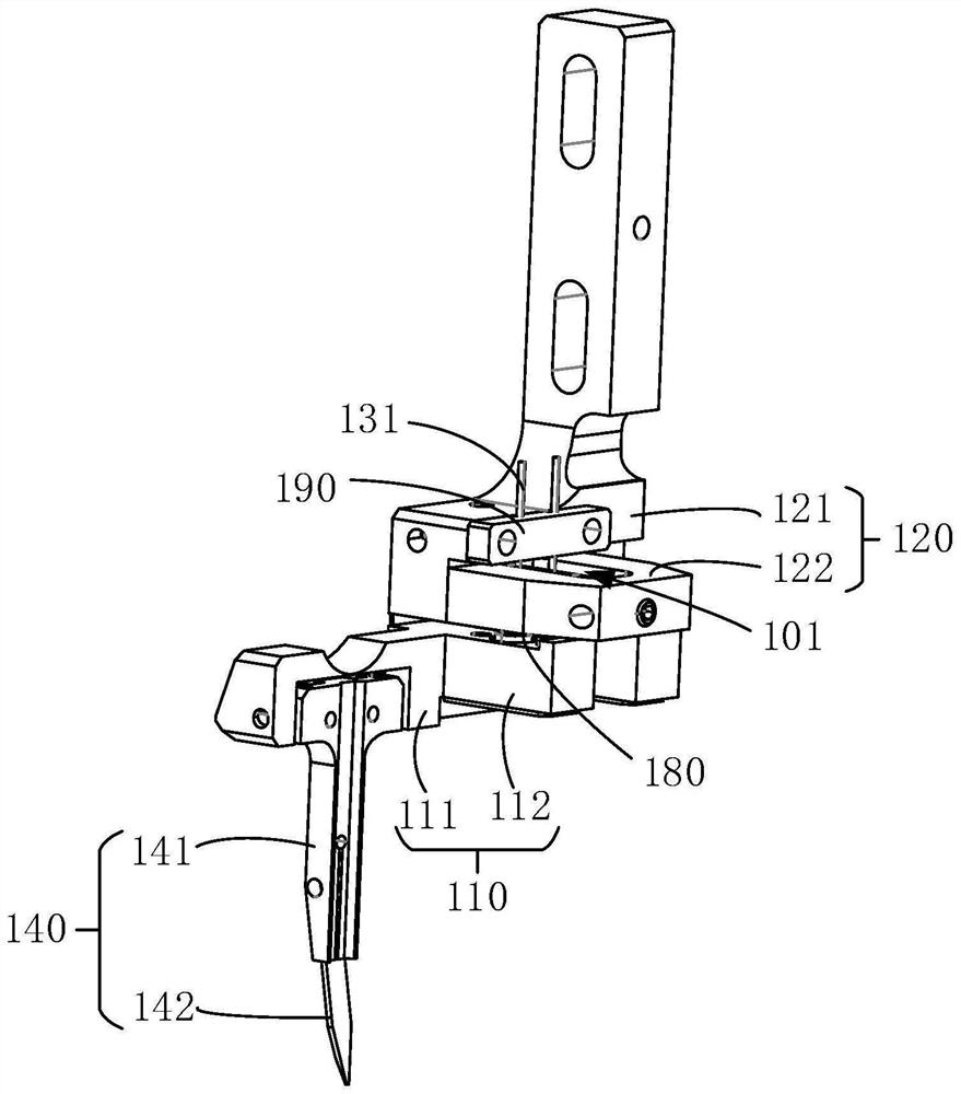
The invention relates to a cutter adjusting device. The cutter adjusting device comprises a cutter holder and a cutter adjusting device, the support is used for being fixedly connected with the equipment body, and a containing groove is formed in the support; the piezoelectric ceramic is arranged in the containing groove, one end of the piezoelectric ceramic abuts against one end of the tool apron, and the other end of the piezoelectric ceramic abuts against the support; the cutter is mounted at the other end of the cutter holder; one end of the first elastic piece is fixedly connected with the support, and the other end of the first elastic piece is fixedly connected with the tool apron; and the control part is electrically connected with the piezoelectric ceramic and is used for driving the piezoelectric ceramic to generate expansion deformation. During line cutting, the piezoelectric ceramic can receive driving voltage sent by the control part to generate expansion deformation, so that force in the second direction can be applied to the upper end of the tool apron, the tool apron can move through elastic deformation of the first elastic piece, the lower end of the tool apron is made to generate displacement, and then the distance of the cutter relative to the chopper is adjusted. Therefore, the cutting length of the aluminum wire can be changed.

Description

technical field [0001] The invention relates to the technical field of semiconductor packaging, in particular to a cutter adjusting device. Background technique [0002] When using ultrasonic bonding technology to weld the aluminum wire and the lead wire of the component to be welded, the aluminum wire is clamped by the chopper and the ultrasonic energy is transmitted to complete the welding of the aluminum wire and the lead wire of the component to be welded. When the welding is done, cut the aluminum wire by the cutter. By adjusting the distance between the cutter and the riving knife, the length of the cut aluminum wire can be controlled. [0003] In the prior art, the cutter is installed on the cutter adjusting device. When utilizing the cutter adjustment device to adjust the distance between the chopper and the cutter, the position of the cutter can only be adjusted manually by loosening the nut of the fixed cutter, and after being adjusted to a suitable position, the...

Claims


Application Information

Patent Timeline
IPC IPC(8): B23K20/10B23K20/26B21F11/00B23K101/36
CPCB23K20/10B23K20/26B21F11/00B23K2101/36
Inventor 盛龙阳纯旭
Owner 深圳市泰达智能装备有限公司
Learn More