Oil pipe unblocking tool

A oil pipe and plugging removal technology, which is applied in the direction of cleaning equipment, wellbore/well parts, earthwork drilling and production, etc., can solve the problems of process pipeline blockage, small flow path, and high hardness of oil pipe wall deposits, etc., to achieve convenient formation , the effect of convenient connection

Pending Publication Date: 2022-05-03
CHINA PETROLEUM & CHEM CORP +1
View PDF2 Cites 2 Cited by
  • Summary
  • Abstract
  • Description
  • Claims
  • Application Information

AI Technical Summary

Problems solved by technology

However, since this tool is mainly used for wellbore desanding operations, for the hard scale and sulfur deposits attached to the inner wall of the tubing, simple flushing is difficult to remove the hard deposits on the inner wall of the tubing, only the soft deposits on the surface are removed. Unplugging effect is not ideal
[0006] In addition, the Chinese utility model patent with the authorized notification number CN210152614U discloses a wax scraping tool for oil pipes, which mainly consists of a central rod and a wax scraping cutter head arranged on the central rod, and is mainly used for oil pipe wax removal operations. For high-sulfur natural gas wells with severe sulfur deposition, due to the small remaining flow path of the tubing and the high hardness of the tubing wall deposits, the use of the tubing wax scraping tool will easily cause the wellbore channel to be further compacted, making it smaller, or even completely jam
At the same time, the massive sediment produced by scraping falls into the wellbore and is carried to the production process after the well is opened for production, which may easily cause blockage of the process pipeline
[0007] To sum up, the plugging removal methods in the prior art all have the problem of unsatisfactory plugging removal effect, so there is an urgent need for a tubing plugging removal tool with better plugging removal effect

Method used


Image

  • Oil pipe unblocking tool
  • Oil pipe unblocking tool
  • Oil pipe unblocking tool

Examples


Embodiment 2

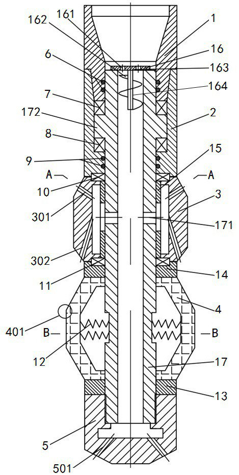
[0060]Embodiment 2 of the oil pipe unblocking tool in the present invention: the difference from the above-mentioned embodiment is that an angular contact ball bearing capable of bearing a certain axial force is used between the mandrel and the bearing sleeve to realize rotational fit. There is no need to set up a ring platform.

Embodiment 3

[0061] Embodiment 3 of the oil pipe unblocking tool of the present invention: the difference from the above embodiments is that no bearing sleeve is provided, and the mandrel is directly rotatably mounted on the inner wall of the upper joint through angular contact ball bearings.

[0062] Embodiment 4 of the oil pipe unblocking tool in the present invention: the difference from the above embodiment is that the rotating lower spray head is not fixedly connected to the bottom of the mandrel, but a bit higher, and a guide head is connected to the bottom of the mandrel , the rotating lower nozzle is located above the guide head, and at this time, a communication hole is provided on the tube wall of the mandrel as a communication structure.

Embodiment 5

[0063] Embodiment 5 of the oil pipe unblocking tool of the present invention: the difference from the above embodiments is that the upper rotating nozzle is not provided with a lower flow hole, but only with an upper flow hole.


PUM


Abstract

The invention provides an oil pipe unblocking tool. The oil pipe unblocking tool comprises an upper connector and a lower connector, the core shaft is rotatably connected to the lower portion of the upper connector, the core shaft is provided with an inner cavity communicated with the upper connector, and a rotation generator used for driving the core shaft to rotate is installed on the core shaft; the rotary lower spray head is fixed on the mandrel so as to synchronously rotate along with the mandrel, the mandrel is provided with a communicating structure for communicating an inner cavity of the mandrel with an inner cavity of the rotary lower spray head, and the rotary lower spray head is provided with a liquid spraying hole for flushing blockages on the inner wall of the oil pipe; and the grinding and milling brush is arranged outside the mandrel and located above the rotary lower spray head, and the grinding and milling brush, the mandrel and the rotary lower spray head rotate together so as to grind blockages on the inner wall of the oil pipe. According to the oil pipe plug removal device, the rotary lower spray head and the milling brush are combined, plugs on the inner wall of an oil pipe can be softened firstly, loose plugs on the surface can be removed, then hard plugs are ground, the good plug removal effect can be achieved, and smooth development of follow-up production cannot be affected.

Description

technical field [0001] The invention relates to the technical field of oil pipe unblocking, in particular to an oil pipe unblocking tool. Background technique [0002] The oil pipe is the production channel of the gas well, and the size of the oil pipe flow channel directly affects the production of the gas well, and is also a prerequisite for the implementation of the gas well operation. Due to the high content of hydrogen sulfide in high-sulfur gas wells, with the development of gas fields, the pressure of gas reservoirs gradually decreases, and a large amount of elemental sulfur is precipitated and adsorbed on the inner wall of the wellbore, resulting in increasingly serious sulfur deposition in the wellbore. . [0003] The commonly used wellbore plugging removal methods include chemical agent plugging removal and mechanical plugging removal. [0004] The main principle of chemical plugging removal is to inject chemicals into the wellbore, and the chemicals react with t...

Claims


Application Information

Patent Timeline
IPC IPC(8): E21B37/00E21B37/02
CPCE21B37/00E21B37/02
Inventor 冯逍宿亚仙鄢标刘方检梁梅生陈刚吴晓磊高士强
Owner CHINA PETROLEUM & CHEM CORP
Why Eureka
Try Eureka