Infrared lamp system for vehicle, infrared sensor system for vehicle, lamp with built-in infrared sensor for vehicle, and lamp with built-in optical sensor

An infrared sensor and infrared technology, applied in optics, headlights, optical components, etc., can solve the problem of pedestrian reflection intensity not being photographed

Pending Publication Date: 2022-04-29
KOITO MFG CO LTD
View PDF5 Cites 0 Cited by
  • Summary
  • Abstract
  • Description
  • Claims
  • Application Information

AI Technical Summary

Problems solved by technology

However, objects with low reflection intensity such as pedestrians may not be captured in the image obtained from the infrared camera in this case

Method used


Image

  • Infrared lamp system for vehicle, infrared sensor system for vehicle, lamp with built-in infrared sensor for vehicle, and lamp with built-in optical sensor
  • Infrared lamp system for vehicle, infrared sensor system for vehicle, lamp with built-in infrared sensor for vehicle, and lamp with built-in optical sensor
  • Infrared lamp system for vehicle, infrared sensor system for vehicle, lamp with built-in infrared sensor for vehicle, and lamp with built-in optical sensor

Examples


Embodiment Construction

[0041] Hereinafter, the present invention will be described based on embodiments with reference to the drawings. The same or equivalent components, components, and processes shown in the drawings are assigned the same symbols, and overlapping descriptions are appropriately omitted. In addition, the embodiment does not limit the invention but is an example, and all the features and combinations thereof described in the embodiment do not necessarily constitute the essence of the present invention.

[0042]

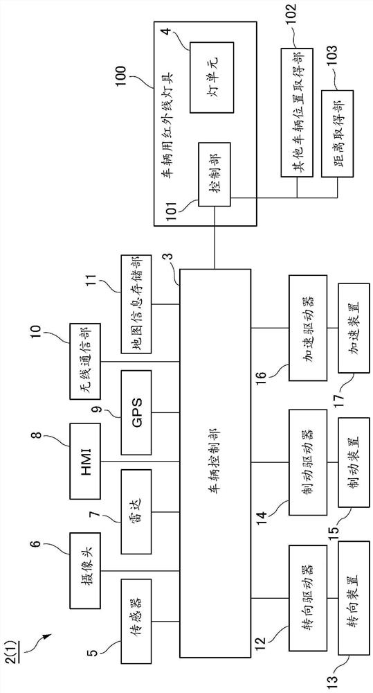
[0043] figure 1 It is a block diagram of the vehicle system 2 incorporating the vehicle infrared lamp system 100 according to the embodiment of the present invention. The vehicle 1 equipped with the vehicle system 2 is a vehicle (motor vehicle) capable of traveling in an automatic driving mode. Such as figure 1 As shown, the vehicle system 2 includes a vehicle control unit 3, a sensor 5, a camera 6, a radar 7, an HMI (Human Machine Interface: Human Machine Interface) 8,...


PUM


Abstract

A vehicle infrared lamp system (100) mounted on a vehicle (1) on which an infrared camera (34) is mounted is provided with: an infrared light source (32); a rotating reflector (33); an other vehicle position acquisition unit (102) that acquires position information of the other vehicle; and a control unit (101). And a control unit (101) that controls the lighting state of the infrared light source (32) on the basis of the position information of the other vehicle acquired by the other vehicle position acquisition unit (102) so as to form, in at least a part of the other vehicle, a light reduction region (Q1) in which the irradiation intensity of infrared rays is lower than the irradiation intensity of the other region (normal region S).

Description

technical field [0001] The present invention relates to a vehicle infrared lamp system, a vehicle infrared sensor system, a vehicle infrared sensor built-in lamp, and an optical sensor built-in lamp for vehicles such as automobiles. Background technique [0002] A scotopic device is known from Patent Document 1 and the like. [0003] Patent Document 1: (Japanese) Unexamined Patent Publication No. 2014-127924 [0004] However, a certain vehicle irradiates infrared rays or increases the intensity of irradiated infrared rays in order to clarify an image obtained by infrared rays. However, when another vehicle such as an oncoming vehicle or a vehicle in front is located in front of the own vehicle, if the other vehicle is irradiated with infrared rays, it will be reflected with a strong intensity, and a halo will be generated on the image of the infrared camera of the own vehicle. When halos are generated in this way, an image without halos can be obtained by reducing the sens...

Claims


Application Information

Patent Timeline
Patent Type & Authority Applications(China)
IPC IPC(8): F21S41/13F21S41/143F21S41/148F21S41/153F21S41/16F21S41/265F21S41/40F21S41/663F21S41/675B60Q1/14B60Q1/24F21S45/00F21W102/145F21Y107/60F21Y113/00F21Y115/10F21Y115/30
CPCF21S41/13F21S41/143F21S41/148F21S41/153F21S41/16F21S41/265F21S41/40F21S41/663F21S41/675B60Q1/14F21S45/00F21W2102/145F21Y2107/60F21Y2113/00F21Y2115/10F21Y2115/30B60Q1/249F21S41/25B60Q1/0023B60Q2300/41B60Q2300/42B60Q2300/45B60Q1/143B60Q2300/056H04N23/74H05B47/125H05B45/325B60Q1/04G02B19/0009G02B19/0076H04N5/33
Inventor 望月光之
Owner KOITO MFG CO LTD
Why Eureka
Try Eureka