
Signal transmission circuit and method of improving quality of signals received by receiving end

A technology for signal transmission and reception, applied in printed circuits, printed circuits, printed circuit components, etc., to solve problems such as low signal quality, common-mode impedance mismatch, and increased common-mode noise

Active Publication Date: 2016-11-09
LANGCHAO ELECTRONIC INFORMATION IND CO LTD
View PDF5 Cites 1 Cited by
  • Summary
  • Abstract
  • Description
  • Claims
  • Application Information

AI Technical Summary

Problems solved by technology

[0004] However, signal quality is affected by two parts, differential impedance and common-mode impedance. The existing technology only considers the influence of differential impedance, which makes the common-mode impedance mismatch, resulting in the increase of common-mode noise due to reflection superposition, which in turn makes low signal quality

Method used


Image

  • Signal transmission circuit and method of improving quality of signals received by receiving end
  • Signal transmission circuit and method of improving quality of signals received by receiving end
  • Signal transmission circuit and method of improving quality of signals received by receiving end

Examples


Embodiment Construction

[0068] In order to make the purpose, technical solutions and advantages of the embodiments of the present invention clearer, the technical solutions in the embodiments of the present invention will be clearly and completely described below in conjunction with the drawings in the embodiments of the present invention. Obviously, the described embodiments It is a part of the embodiments of the present invention, but not all of them. Based on the embodiments of the present invention, all other embodiments obtained by those of ordinary skill in the art without creative work belong to the protection of the present invention. scope.

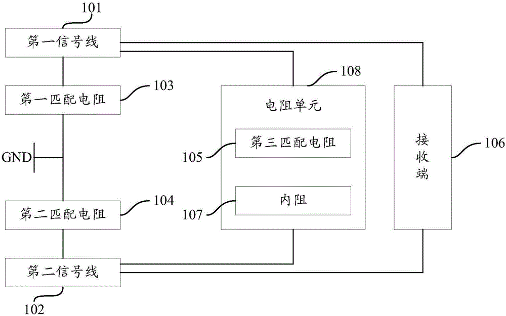
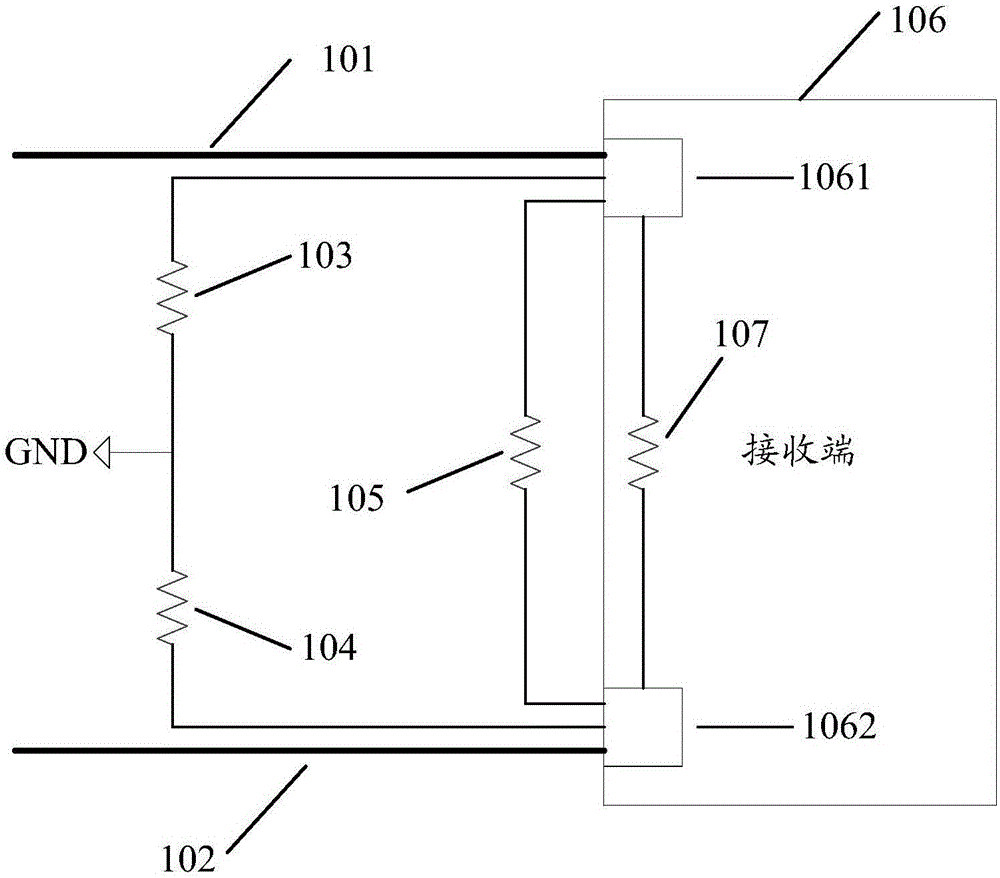
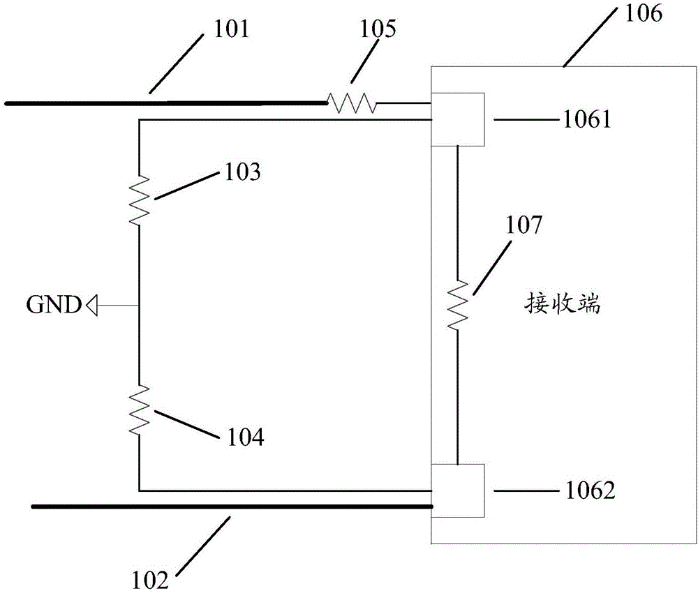
[0069] Such as figure 1 As shown, the embodiment of the present invention provides a signal transmission circuit, including:

[0070] A first signal line 101 and a second signal line 102 for transmitting signals, a first matching resistor 103, a second matching resistor 104, a third matching resistor 105, and a receiving terminal 106;

[0071] The fir...


PUM


Abstract

The invention provides a signal transmission circuit and a method of improving quality of signals received by a receiving end. The signal transmission circuit comprises a first signal line and a second signal line, which are used to transmit signals; a first matching resistor, a second matching resistor, a third matching resistor, and a receiving end. The first signal line is connected with the first terminal of the receiving end, and the second signal line is connected with the second terminal of the receiving end. The first end of the first matching resistor is connected with the first signal line, and the second end is grounded. The first end of the second matching resistor is connected with the second signal line, and the second end is grounded. A first end of a resistor unit formed by the third matching resistor and the internal resistor of the receiving end is connected with the first signal line, and the second end is connected with the second signal line. The first matching resistor, the second matching resistor, and the resistor unit are matched with the differential impedance and the common mode impedance of the first signal line and the second signal line. By adopting the signal transmission circuit and the method of improving the quality of the signals received by the receiving end, the quality of the signals is improved.

Description

technical field [0001] The invention relates to the field of electronic technology, in particular to a signal transmission circuit and a method for improving the quality of a signal received by a receiving end. Background technique [0002] In PCB (Printed Circuit Board, printed circuit board), in order to improve the quality of signal transmission, the method of differential transmission is often used to transmit signals, specifically, the signal is transmitted through two signal lines, the two signal lines The signal amplitude is equal and the phase is opposite. The signal received by the receiving end is equal to the difference between two complementary and mutually referenced signals. Therefore, the electrical noise effect of the signal can be greatly reduced. However, in the process of signal transmission on the signal line, due to the interference of the differential impedance and common mode impedance of the transmission line, the quality of the signal will be reduced...

Claims


Application Information

Patent Timeline
IPC IPC(8): H05K1/02
CPCH05K1/025H05K2201/0776
Inventor 武宁李永翠
Owner LANGCHAO ELECTRONIC INFORMATION IND CO LTD
Learn More