
Induction power taking method, system and equipment for overhead line and storage medium

An overhead line and induction power-taking technology, which is applied in the field of power systems, can solve the problems of increasing device maintenance costs, staff workload, low reliability and power density, and limited battery capacity, so as to reduce maintenance costs and workload. Easy to install, good effect

Pending Publication Date: 2022-04-29
XI AN JIAOTONG UNIV
View PDF0 Cites 0 Cited by
  • Summary
  • Abstract
  • Description
  • Claims
  • Application Information

AI Technical Summary

Problems solved by technology

Some online monitoring devices use batteries for power supply, but the battery capacity is limited and the running time is short. The battery of the device must be replaced before the end of the battery life to run normally, which greatly increases the maintenance cost of the device and the workload of the staff
In addition, the power supply of some online monitoring devices is realized by converting the energy near the overhead line into electric energy. There are many potential energy sources near the overhead line, such as solar energy and wind energy, but solar energy and wind energy are less affected by the environment and weather conditions. Large, its reliability and power density are low, and its power supply capability is poor

Method used

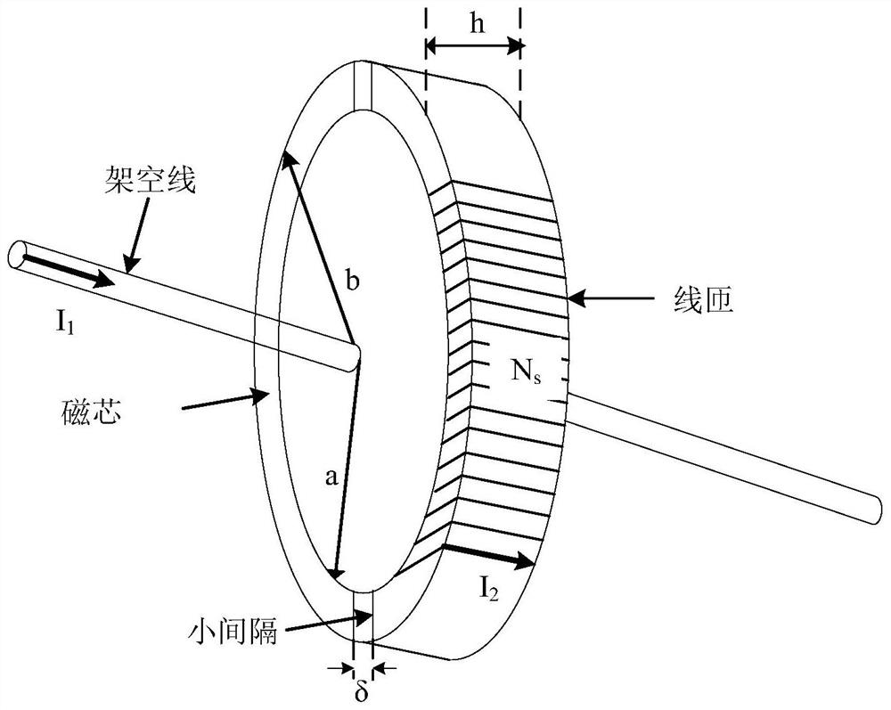
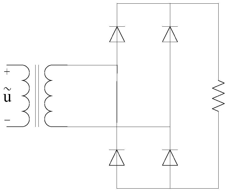

Image

  • Induction power taking method, system and equipment for overhead line and storage medium
  • Induction power taking method, system and equipment for overhead line and storage medium
  • Induction power taking method, system and equipment for overhead line and storage medium

Examples


Embodiment Construction

[0033] The technical solutions in the embodiments of the present invention will be clearly and completely described below in conjunction with the accompanying drawings in the embodiments of the present invention. Obviously, the described embodiments are only some of the embodiments of the present invention, not all of them; based on The embodiments of the present invention and all other embodiments obtained by persons of ordinary skill in the art without making creative efforts belong to the protection scope of the present invention.

[0034] It should be noted that the words "front", "rear", "left", "right", "upper" and "lower" used in the following description refer to the directions in the drawings, and the words "inner" and "outer ” refer to directions towards or away from the geometric center of a particular part, respectively.

[0035] Unless otherwise defined, all technical and scientific terms used herein have the same meaning as commonly understood by one of ordinary ...


PUM


Abstract

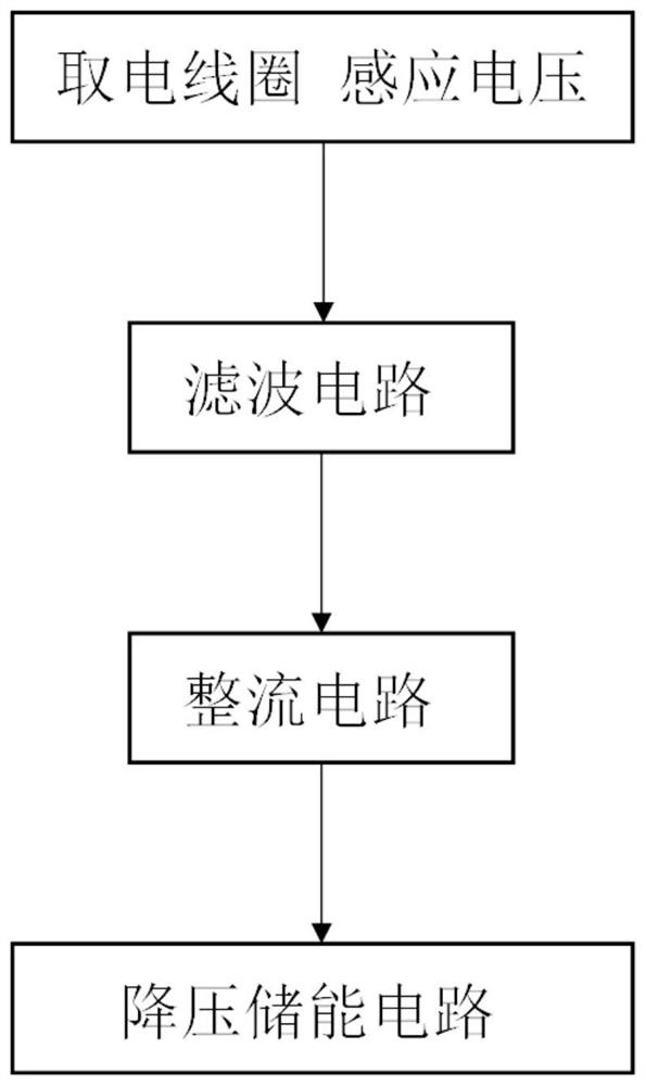
The invention discloses an overhead line induction power taking method, system and device and a storage medium. The method comprises the following steps: S1, collecting magnetic field energy of an overhead line and converting the magnetic field energy into alternating voltage; s2, rectifying the alternating current voltage; s3, the rectified voltage is filtered; and S4, after voltage reduction and energy storage are carried out on the filtered voltage through a voltage reduction and energy storage circuit, the voltage is output to an online monitoring device on the overhead line. Required direct-current voltage can be stably output through the rectifying circuit, the filter circuit and the step-down energy storage circuit, reliable and stable power supply can be achieved for an on-line monitoring device on an overhead line, the cost is low, and the effect is good. The magnetic field energy on the overhead line is used for induction power taking, the maintenance cost and the workload caused when a storage battery is used for supplying power are greatly reduced, the device is easy to install, and the original structure of the overhead line cannot be affected.

Description

technical field [0001] The invention belongs to the field of electric power systems, and relates to a method, system, equipment and storage medium for inductive power acquisition of overhead lines. Background technique [0002] With the rapid development of smart grid, the power system has stricter requirements on power supply reliability, efficiency and security. In order to ensure the safety and reliability of power transmission and distribution, it is necessary to monitor the parameters and status of overhead lines. The detection and diagnosis device installed on the overhead line can effectively detect the real-time temperature, humidity, surrounding wind speed, load condition, line condition, insulator degradation, nearby interference and other parameters of the line, so as to judge the operation status of the line, which can help the staff to timely Find out the potential hidden dangers of overhead lines and deal with them as soon as possible, so as to effectively red...

Claims


Application Information

Patent Timeline
Patent Type & Authority Applications(China)
IPC IPC(8): H02J50/10H02J7/04H02J9/06H02J7/34
CPCH02J50/001H02J50/005H02J50/10H02J7/04H02J9/068H02J7/345H02J2207/20H02J2207/50
Inventor 唐锟陶嘉琦陈俊百岳显雨李洪杰
Owner XI AN JIAOTONG UNIV
Learn More