A cooling and ventilating structure of a motor controller for a scooter

A technology of motor controller and scooter, which is applied in the direction of motor control, control system, support structure installation, etc. It can solve the problems of loosening of screws fixing the motor controller, easy heat accumulation, and burning of the motor controller chip, so as to prevent screw Loosening, reducing impact, and easy installation

Active Publication Date: 2022-06-28
深圳市永锋顺科技有限公司
View PDF8 Cites 0 Cited by
  • Summary
  • Abstract
  • Description
  • Claims
  • Application Information

AI Technical Summary

Problems solved by technology

[0002] The motor controller is a module responsible for controlling the power output motor in the scooter. The motor controller includes a control module. During use, the chip in the control module will generate a lot of heat, which will affect the motor controller when it reaches a certain temperature. The normal use of the motor controller will even burn the chip in the motor controller, which will affect the service life of the scooter, and the traditional scooter shell is to ensure waterproof, so the scooter shell is a closed environment, and the heat generated by the chip cannot be effectively dissipated. very easy to accumulate heat
[0003] The motor controller is the core component of the scooter, which contains multiple precision modules. In order to protect the safety of the motor controller, the motor controller is often fixed and protected in multiple directions. The reason is that the fixed motor controller will be subject to vibration. Long-term vibration will loosen the screws used to fix the motor controller, which will affect the stability of the motor controller. In order to protect the motor controller and enable the motor controller to get effective heat dissipation, it is necessary Propose a cooling and ventilation structure for the motor controller of the scooter

Method used


Image

  • A cooling and ventilating structure of a motor controller for a scooter
  • A cooling and ventilating structure of a motor controller for a scooter
  • A cooling and ventilating structure of a motor controller for a scooter

Examples


Embodiment Construction

[0035] The technical solutions in the embodiments of the present invention will be clearly and completely described below with reference to the accompanying drawings in the embodiments of the present invention. Obviously, the described embodiments are only a part of the embodiments of the present invention, rather than all the embodiments. In order to To simplify the disclosure of the present invention, specific example components and arrangements are described below, which, of course, are merely examples and are not intended to limit the present invention.

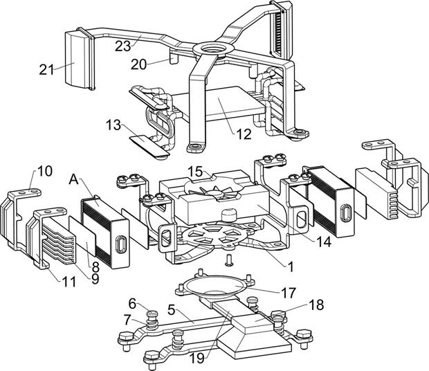
[0036] Hereinafter, the heat dissipation and ventilation structure of the motor controller for the scooter according to the embodiment of the present invention will be described with reference to the accompanying drawings, such as figure 1 - Figure 12 As shown, the heat dissipation and ventilation structure of the motor controller for the scooter includes a mounting plate 1, a support plate 5, a sliding rod 6, a first sp...


PUM


Abstract

The invention discloses a heat dissipation and ventilation structure for a motor controller of a scooter, which comprises a mounting plate, a support plate, a slide bar, a first spring, a heat dissipation device capable of dissipating heat from the side of the motor controller, and a cooling device capable of cooling the motor controller. The ventilation device for heat conduction and heat dissipation, the convection device that allows the outside air to enter when the scooter is running, the support plate is fixed inside the scooter, the mounting plate is slidably installed on the support plate through a slider, and the connection between the mounting plate and the support plate The first spring is connected between them, the heat dissipation device is arranged on both sides of the installation plate, the ventilation device is arranged on the upper and lower sides of the installation board, and the convection device is arranged on the top of the ventilation device. Packed heat conduction allows the heat generated by the motor controller to conduct to the heat conduction plate, and then use the fan to dissipate heat.

Description

technical field [0001] The invention relates to the electromechanical field, in particular to a heat dissipation and ventilation structure for a motor controller of a scooter. Background technique [0002] The motor controller is a module responsible for controlling the power output motor in the scooter. The motor controller includes a control module. During use, the chip in the control module will generate a lot of heat, and when it reaches a certain temperature, it will affect the motor controller. The normal use of the scooter will even burn the chip in the motor controller, affecting the service life of the scooter, and the traditional scooter shell is to ensure waterproofness, so the scooter shell is a closed environment, and the heat generated by the chip cannot be effectively dissipated. Very easy to heat up. [0003] The motor controller is the core component of the scooter, which contains multiple precision modules. In order to protect the safety of the motor contr...

Claims


Application Information

Patent Timeline
Patent Type & Authority Patents(China)
IPC IPC(8): H05K7/14F16F15/067H05K7/20H02P29/00
CPCH05K7/14F16F15/067H05K7/209H05K7/20918H05K7/2089H05K7/20127H02P29/00
Inventor 李小芹
Owner 深圳市永锋顺科技有限公司
Why Eureka
Try Eureka