Biosensor for detecting MicroRNA-17
A biosensor and protein technology, applied in the field of sensors, can solve the problems of complex experimental process, low sensitivity, limitations, etc., and achieve the effects of low process cost, sensitive detection, and easy operation.
- Summary
- Abstract
- Description
- Claims
- Application Information
AI Technical Summary
Problems solved by technology
Method used
Image

Examples
Embodiment 1
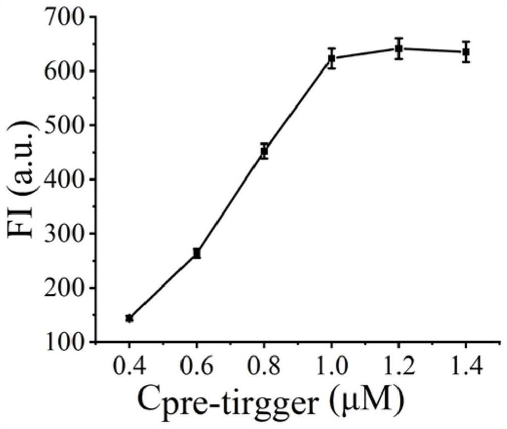
[0034] Example 1 Pre-trigger concentration optimization
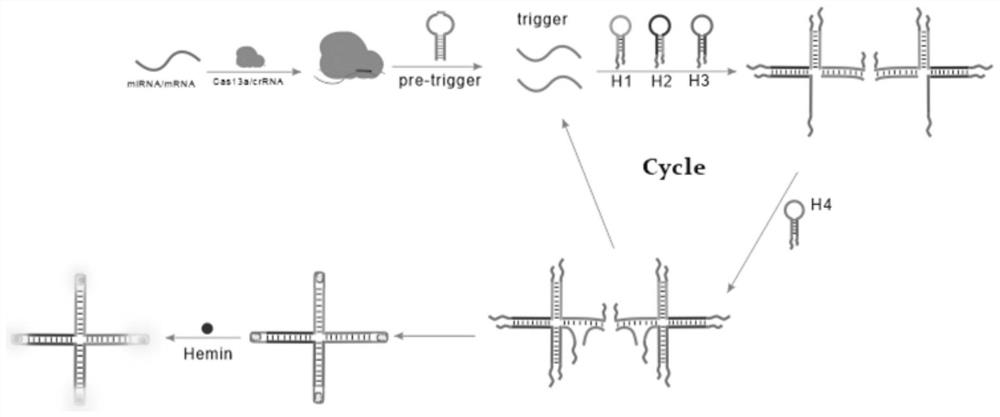
[0035] (1) In a 1.5 mL centrifuge tube, add hairpin pre-trigger (final concentrations are 0.4 μM, 0.6 μM, 0.8 μM, 1.0 μM, 1.2 μM, 1.4 μM), H1 (10 μM), H2 (10 μM ), H3 (10 µM), H4 (10 µM) 10 µL each, add 10 µL 10×buffer2.1, shake and mix well, put in 95°C water bath for 5 min, then cool to room temperature;
[0036] (2) Add 2 µL of cas13a protein (100 nM), 2 µL of crRNA (50 nM), 1 µL of miRNA-17, and 26.7 µL of sterilized water into the solution obtained above, and place the centrifuge tube in a 37°C water bath for reaction 75 minutes;
[0037] (3) Add 3 µL of heme, 3 µL of luminol reagent, and 3.3 µL of hydrogen peroxide, and detect the peak of chemiluminescence at 420 nm with a fluorometer. The measurement range of chemiluminescence spectrum is 400 nm to 600 nm, read the change of fluorescence signal, and detect the target object;
[0038] see results figure 2 , it can be seen from the figure that the detected pea...
Embodiment 2
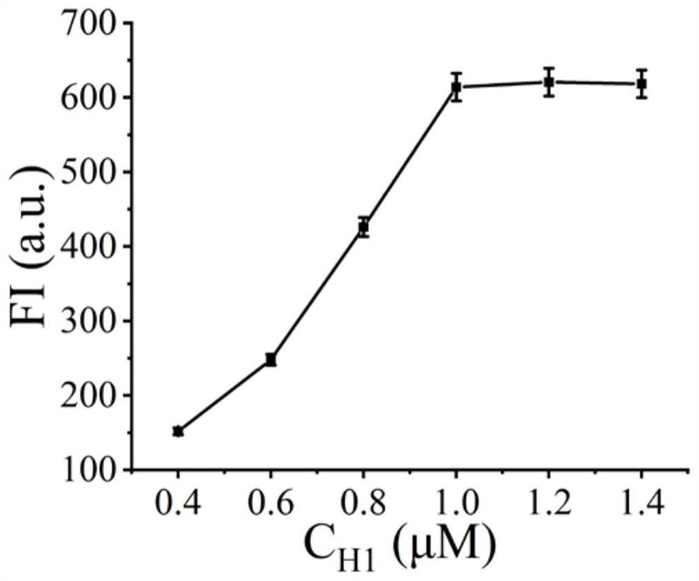
[0039] Example 2 H1 concentration optimization
[0040] (1) In a 1.5 mL centrifuge tube, add hairpin pre-trigger (10 µM), H1 (final concentrations are 0.4 µM, 0.6 µM, 0.8 µM, 1.0 µM, 1.2 µM, 1.4 µM), H2 (10 µM ), H3 (10 µM), H4 (10 µM) 10 µL each, add 10 µL 10×buffer2.1, shake and mix well, put in 95°C water bath for 5 min, then cool to room temperature;
[0041] (2) Add 2 µL of cas13a protein (100 nM), 2 µL of crRNA (50 nM), 1 µL of miRNA-17, and 26.7 µL of sterilized water into the solution obtained above, and place the centrifuge tube in a 37°C water bath for reaction 75 minutes;
[0042] (3) Add 3 µL of heme, 3 µL of luminol reagent, and 3.3 µL of hydrogen peroxide, and detect the peak of chemiluminescence at 420 nm with a fluorometer. The measurement range of chemiluminescence spectrum is 400 nm to 600 nm, read the change of fluorescence signal, and detect the target object;
[0043] see results image 3 , it can be seen from the figure that the detected peak chemilum...
Embodiment 3
[0044] Embodiment 3 reaction time optimization
[0045](1) In a 1.5 mL centrifuge tube, add 10 µL each of hairpin pre-trigger (10 µM), H1 (10 µM), H2 (10 µM), H3 (10 µM), H4 (10 µM), and add 10 µL10×buffer2.1, vortex and mix well, put in 95℃ water bath for 5min, then cool to room temperature;
[0046] (2) Add 2 µL of cas13a protein (100 nM), 2 µL of crRNA (50 nM), 1 µL of miRNA-17, and 26.7 µL of sterilized water into the solution obtained above, and place the centrifuge tube in a 37°C water bath for reaction 30 min, 45 min, 60 min, 75 min, 90 min, 105 min, 120 min;
[0047] (3) Add 3 µL of heme, 3 µL of luminol reagent, and 3.3 µL of hydrogen peroxide, and detect the peak of chemiluminescence at 420 nm with a fluorometer. The measurement range of chemiluminescence spectrum is 400 nm to 600 nm, read the change of fluorescence signal, and detect the target object;
[0048] see results image 3 , it can be seen from the figure that the detected peak chemiluminescence intensi...
PUM
 Abstract
Description
Claims
Application Information
 - R&D
- Intellectual Property
- Life Sciences
- Materials
- Tech Scout
- Unparalleled Data Quality
- Higher Quality Content
- 60% Fewer Hallucinations
Browse by: Latest US Patents, China's latest patents, Technical Efficacy Thesaurus, Application Domain, Technology Topic, Popular Technical Reports.
© 2025 PatSnap. All rights reserved.Legal|Privacy policy|Modern Slavery Act Transparency Statement|Sitemap|About US| Contact US: help@patsnap.com