Target point cloud segmentation method applied to turbine blade film hole detection

A technology of turbine blades and gas film holes, which is applied in image analysis, measuring devices, optical devices, etc., can solve problems such as large impact on edge detection accuracy, over-segmentation, and difficulty in ensuring segmentation accuracy, so as to avoid unstable segmentation results Effect

Active Publication Date: 2022-04-22
SHANGHAI JIAO TONG UNIV
View PDF4 Cites 4 Cited by
  • Summary
  • Abstract
  • Description
  • Claims
  • Application Information

AI Technical Summary

Problems solved by technology

The edge detection method that takes the geometric edge of the point cloud as the dividing line mostly regards the direction vector or the sudden change of curvature of the point cloud as the area boundary, and then realizes the purpose of point cloud segmentation in the target area, but the algorithm is greatly affected by the edge detection accuracy. Due to the influence of factors such as point cloud noise, normal vector solution accuracy, and curvature error, under-segmentation or over-segmentation are prone to occur.
In addition, by selecting the region growing method of a specific seed point, according to the corresponding growth strategy to grow and expand to the adjacent points until there are no more points that meet the growth strategy, the purpose of point cloud segmentation in the target region can also be achieved, but due to the initial seed point The distribution position and the formulation of the growth strategy, the segmentation accuracy is difficult to guarantee, and there is no mature seed point selection and growth strategy that can be applied to the segmentation of the gas film hole target point cloud.

Method used


Image

  • Target point cloud segmentation method applied to turbine blade film hole detection
  • Target point cloud segmentation method applied to turbine blade film hole detection
  • Target point cloud segmentation method applied to turbine blade film hole detection

Examples


Embodiment Construction

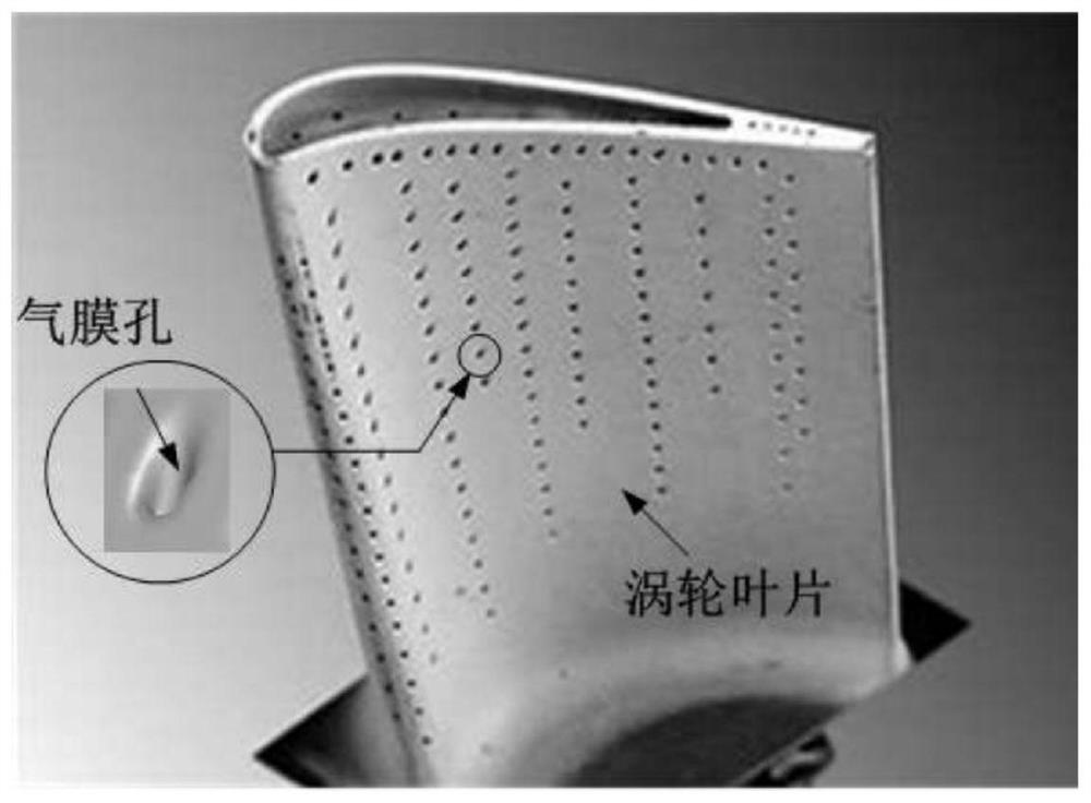
[0026] Such as Image 6 As shown, this embodiment involves an application such as figure 1 In the shown target point cloud segmentation method applied to the detection of air film holes in aeroengine turbine blades, the air film holes on the blades are the target point cloud regions of the segmentation method in the present invention.

[0027] This embodiment includes the following steps:

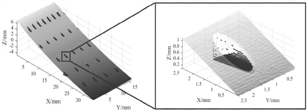
[0028] Step 1) Turbine blade laser point cloud scanning: through the five-axis laser measurement platform, the three-dimensional point cloud of the turbine blade space is collected by multi-position scanning, such as figure 2 shown.

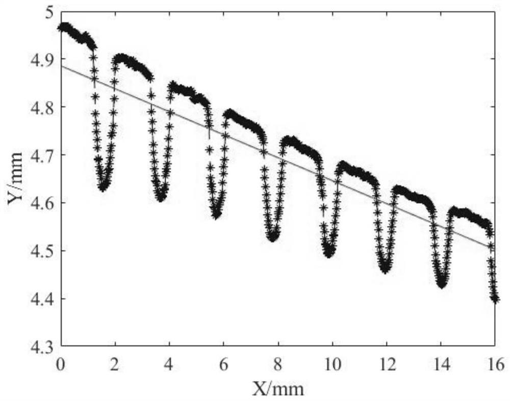
[0029] Step 2) Scan point cloud slice: based on the laser sensor measurement trajectory and the distribution characteristics of the laser point cloud, slice the scanned point cloud in the forward direction, and project it on the XZ plane into a two-dimensional point cloud slice unit d with a length of 16 mm in the X direction i (i=1,2,3,...,n), initialize ...


PUM


Abstract

A target point cloud segmentation method applied to turbine blade film hole detection comprises the following steps: acquiring spatial three-dimensional point cloud data of a to-be-detected turbine blade through a five-axis laser measurement platform, and carrying out spatial slicing dimension reduction processing on the blade laser point cloud data in the advancing direction according to a measurement track and laser point cloud distribution characteristics of a laser sensor, so as to obtain a target point cloud data of the to-be-detected turbine blade; calculating a straight line fitting residual by combining the gradient distribution characteristics of the point cloud data of each slice, and screening the point cloud slices of the film hole region; on the basis, carrying out detrending processing on the screened point cloud slices to obtain fitting error class horizontal lines of the slices; a target point set on each slice is obtained through threshold value screening, film hole target area point cloud segmentation is realized, then axis direction and aperture size extraction is carried out on the film hole target area point cloud, quality detection of turbine blade film holes is realized, and thus the point cloud segmentation precision is obviously improved.

Description

technical field [0001] The invention relates to a technology in the field of aero-engine manufacturing, in particular to a target point cloud segmentation method applied to the detection of gas film holes in turbine blades. Background technique [0002] In order to ensure the reliability of aero-engines under high mechanical loads, the axial direction and aperture size of the air film holes in turbine blades have strict precision requirements. The air film hole feature detection algorithm based on laser point cloud can perform high-precision detection of air film holes. Quality Inspection. However, the 3D point cloud of the blade space collected by the line laser sensor, in addition to the point cloud data of the gas film hole in the target area, also includes the point cloud of the blade surface and the noise point cloud, which cannot be directly used for the extraction of the geometric feature of the gas film hole space. Therefore, it is also necessary to use the air film...

Claims


Application Information

Patent Timeline
Patent Type & Authority Applications(China)
IPC IPC(8): G01B11/00G01B11/12G06T7/10
CPCG01B11/00G01B11/12G06T7/10G06T2207/10028
Inventor 奚学程张敏闫晓燊高强朱思萌张亚欧赵万生
Owner SHANGHAI JIAO TONG UNIV
Why Eureka
Try Eureka