
Injection molding machine with heat preservation structure

A technology for injection molding machines and injection devices, which is applied in the field of injection molding machines with thermal insulation structures, which can solve the problems of inconvenient fixing and removing of hoppers, inconvenient movement and fixing, and early cooling of plastics, so as to avoid early solidification and heat The effect of less loss, easy cleaning and cleaning

Pending Publication Date: 2022-04-22
瞿壮
View PDF0 Cites 0 Cited by
  • Summary
  • Abstract
  • Description
  • Claims
  • Application Information

AI Technical Summary

Problems solved by technology

[0007] The invention provides an injection molding machine with a thermal insulation structure, one purpose of which is to have the effect of thermal insulation of the plastic in the barrel, and solve the problem of the poor thermal insulation performance of the plastic in the barrel of the existing injection molding machine. The problem of cooling in advance; another purpose is to solve the problem that the existing injection molding machine is inconvenient to fix and remove the hopper, so as to achieve the effect of conveniently taking and fixing the hopper; another purpose is to Solve the problem that the existing injection molding machine is very inconvenient when moving and fixing, so as to achieve the effect of conveniently moving and fixing the injection molding machine

Method used


Image

  • Injection molding machine with heat preservation structure
  • Injection molding machine with heat preservation structure
  • Injection molding machine with heat preservation structure

Examples


Embodiment 1

[0038] Such as Figure 1-6As shown, the present invention provides an injection molding machine with an insulating structure, including the injection molding machine body 1, the top end of the injection molding machine body 1 fixedly connected to the injection device 11, the left side of the injection device 11 fixedly connected to the bucket 2, the bucket 2 The left side of the injection mold 3 is fixed to the left, and the top portion of the injection device 11 is fixedly coupled to the hopper fixing mechanism 4, and the top of the hopper fixing mechanism 4 is provided with a hopper 41, and the side surface of the injection molding machine body 1 is provided with a moving mechanism 5, the bucket 2 Including the inner tube 21, the bucket inner tube 21 is fixedly attached to the left side of the injection device 11, and the outer side of the binder 21 is fixedly coupled to the heat conductance plate 22, the outer side of the heat transfer plate 22 is fixedly connected to the outer ...

Embodiment 2

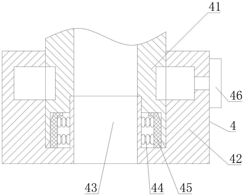
[0041] Such as Figure 1-6 As shown in the basis of the first embodiment, the present invention provides a technical solution: preferably, the hopper fixing mechanism 4 includes a fixing seat 42, and the fixing seat 42 is fixedly attached to the top end of the injection device 11, and the inside of the fixed seat 42 is provided. The venting tube 43, the side surface of the bladder 43 is fixedly connected to the top tightening spring 44, and the sideways of the top-tighten spring 44 are fixedly connected to the top fasten plate 45, and the central portion of the fixing seat 42 is provided with a tensioning mechanism 46, the tensioning mechanism 46 includes The knob 461, the knob 461 is disposed on the side surface of the mount 42, and the left end of the knob 461 is connected to the drive wheel 462, and the side engagement of the active wheel 462 is connected to the driven wheel 463, the left end fixed connection of the driven wheel 463 has a first screw 464, first The side thread o...

Embodiment 3

[0044] Such as Figure 1-6 As shown in the basis of the first embodiment, the present invention provides a technical solution: preferably, the moving mechanism 5 includes a driving handle 51, the drive handle 51 is disposed on the side of the injection molding machine body 1, and the left end fixed connection of the drive handle 51 is provided. The second screw 52, ​​the second screw 52 is disposed inside the injection molding machine body 1, and the side thread of the second screw 52 is connected to the second slider 53, the bottom end activity of the second slider 53 is connected to the push plate 54, the push plate On both sides of the bottom end of the 54, the support leg 55 is fixed, and the bottom end of the support leg 55 is fixedly connected to the moving wheel 56, and the bottom end of the push plate 54 is fixed to the connecting cushion spring 57, the top of the push plate 54 is a trapezoidal structure, push The top of the plate 54 is opened, and the side activity of the ...


PUM


Abstract

The invention discloses an injection molding machine with a heat preservation structure, and relates to the technical field of injection molding machine equipment.The injection molding machine comprises an injection molding machine body, an injection device is fixedly connected to the top end of the injection molding machine body, a material barrel is fixedly connected to the left side of the injection device, and an injection mold is fixedly connected to the left side of the material barrel; a hopper fixing mechanism is fixedly connected to the top of the injection device, a hopper is arranged at the top of the hopper fixing mechanism, and a moving mechanism is arranged on the side face of the injection molding machine body. Through mutual cooperation of the material barrel inner pipe, the heat conduction plate, the heating device, the material barrel outer pipe, heat preservation cotton and a protective sleeve, plastic in the material barrel can be continuously heated through the arrangement of the heat conduction plate and the heating device, and through the arrangement of the heat preservation cotton and the protective sleeve, heat loss is avoided; the injection molding machine solves the problem that plastic is cooled in advance due to the fact that an existing injection molding machine is poor in heat preservation performance of the plastic in a material barrel, prevents the plastic from being solidified in advance, and facilitates forming of workpieces.

Description

Technical field [0001] The present invention relates to an injection molding machine involving the technical field of injection molding machine equipment, and more particularly to an injection molding machine with an insulating structure. Background technique [0002] Plastic processing injection molding machine is also known as a molding machine or a syringe, which is a main molding apparatus for making a thermoplastic or thermosetting material into a variety of plastic molded molds, plastic processing injection molding machine according to injection devices and lock modes The arrangement of the device can be divided into vertical, horizontal and vertical complexes, generally including: injection, heating, discharge, and injection molding steps during the processing of plastic injection molding machine. [0003] There is the following issues for the prior art: [0004] 1. Existing injection molding machines are poor in the bucket, which is easy to make plastics when the plastic ...

Claims


Application Information

Patent Timeline
Patent Type & Authority Applications(China)
IPC IPC(8): B29C45/18B29C45/74B29C45/17
CPCB29C45/18B29C45/74B29C45/17B29C45/1761B29C2045/1784
Inventor 瞿壮
Owner 瞿壮
Learn More