
Novel drill bit for high-precision internal threads and using method of novel drill bit

An internal thread, high-precision technology, applied in the direction of thread cutting tools, metal processing equipment, manufacturing tools, etc., can solve the problems of affecting machining accuracy, clamping deviation, and difficulty in obtaining high precision, so as to improve efficiency, reduce wear, and improve load effect

Active Publication Date: 2022-04-22
ZHENJIANG ZHENGKAI ELECTRONICS
View PDF7 Cites 0 Cited by
  • Summary
  • Abstract
  • Description
  • Claims
  • Application Information

AI Technical Summary

Problems solved by technology

[0003]At present, the tap is used for extrusion cutting. The size and accuracy of the cut thread are obtained by the production of the tap, and at the same time, it is affected by the material properties of the processed workpiece. It is difficult to obtain high precision. A single-edged milling cutter is used for cutting. The single-edged milling cutter rotates radially to form cutting power. At the same time, the machine tool controls radial feed and radial trajectory movement. The combination of the two realizes the processing of the thread. The clamping deviation caused by secondary processing affects the improvement of processing accuracy

Method used


Image

  • Novel drill bit for high-precision internal threads and using method of novel drill bit
  • Novel drill bit for high-precision internal threads and using method of novel drill bit
  • Novel drill bit for high-precision internal threads and using method of novel drill bit

Examples


Embodiment Construction

[0027] The following will clearly and completely describe the technical solutions in the embodiments of the present invention with reference to the drawings in the embodiments of the present invention.

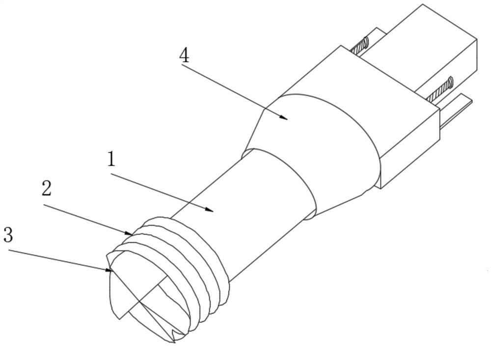
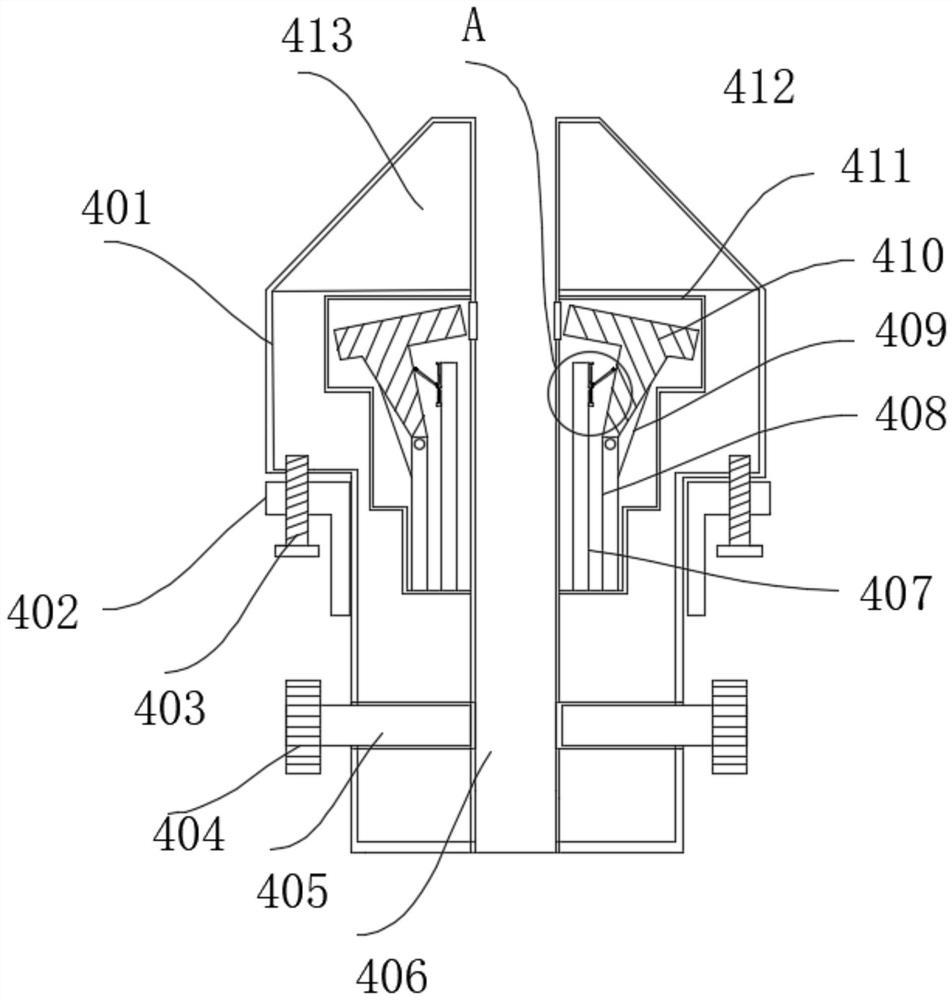
[0028] In order to realize the one-time processing of the internal thread and improve the processing efficiency, refer to figure 1 , Figure 4 with Figure 5 As shown, it includes a support rod 1 plugged into the control end of the machine tool. The side of the support rod 1 away from the control end of the machine tool is provided with a tool for opening high-precision internal threads. The side wall cutting edge on the side is provided with a plurality of side milling edges 2 at equidistant intervals around the side wall cutting edge. An end milling cutter is arranged on the side of the side wall cutting edge away from the support rod 1. The surface of the end milling cutter is There are multiple face milling edges 3, innovatively combining side milling edges and end face ...


PUM


Abstract

The invention discloses a novel drill bit for high-precision internal threads and a using method thereof. The novel drill bit comprises a supporting rod inserted into the control end of a machine tool, and a cutter used for forming the high-precision internal threads is arranged on the side, away from the control end of the machine tool, of the supporting rod; the cutter comprises a side wall cutting edge arranged on the side, away from the machine tool control end, of the supporting rod, a plurality of side face milling cutting edges are formed around the side wall cutting edge at equal intervals, an end face milling cutter is arranged on the side, away from the supporting rod, of the side wall cutting edge, and a plurality of end face milling cutting edges are formed in the surface of the end face milling cutter. A combined end face milling cutter and a side wall cutting edge are creatively combined, the novel milling cutter rotates in the radial direction to form cutting power, meanwhile, a machine tool controls radial feeding and radial track movement, the end face milling edge is used for machining a hole in the surface of a workpiece in the radial feeding process, and the side wall single milling edge is optimally increased to be two or more. The milling resistance of each single blade is reduced; one-time machining of the threads is achieved through combination of the two methods, and efficiency is improved by more than one time.

Description

technical field [0001] The invention belongs to the technical field of internal thread processing, and in particular relates to a novel drill bit for high-precision internal thread and a use method thereof. Background technique [0002] Female threads are not exposed, usually on the side of the rotary fastener being rotated. The groove bottom of the internal thread can be arc-shaped. If the shape of the groove bottom of the thread tooth is not specified, it can be flattened or rounded during turning. When threading, use a tap for extrusion cutting or a single-edged milling cutter for cutting Machining to achieve the desired thread. [0003] At present, the thread tap is used for extrusion cutting. The size and accuracy of the thread cutting are obtained by the production of the thread tap. At the same time, it is affected by the material properties of the workpiece to be processed. It is difficult to obtain high precision. A single-edged milling cutter is used for cutting. ...

Claims


Application Information

Patent Timeline
IPC IPC(8): B23G5/18
CPCB23G5/18
Inventor 胡祥
Owner ZHENJIANG ZHENGKAI ELECTRONICS
Learn More