
Overheating deformation ventilation type transformer

A transformer and deformation technology, applied in the field of transformers, can solve the problems of transformer components burnt, dust, water vapor blocking, poor heat dissipation, etc., and achieve the effect of expanding the ventilation area and improving the heat dissipation effect

Pending Publication Date: 2022-04-19
王德彬
View PDF0 Cites 2 Cited by
  • Summary
  • Abstract
  • Description
  • Claims
  • Application Information

AI Technical Summary

Problems solved by technology

However, when the transformer is working, a lot of heat will be generated inside. If the internal heat of the transformer is too high, it will cause the internal components of the transformer to burn out, which is not conducive to the use of the transformer.
[0003] At present, when the existing transformers dissipate heat, most of them dissipate heat through the cooling grooves opened on both sides or the heat sinks installed on the end wall of the transformer. However, it is not easy to block dust and water vapor when the temperature is lowered, that is, when there is no need to dissipate heat. If only heat sinks are installed, heat dissipation will only be carried out through contact heat transfer, and it is difficult to achieve internal and external ventilation.

Method used


Image

  • Overheating deformation ventilation type transformer
  • Overheating deformation ventilation type transformer
  • Overheating deformation ventilation type transformer

Examples


Embodiment 1

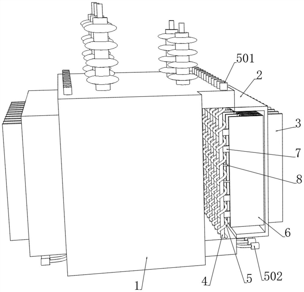
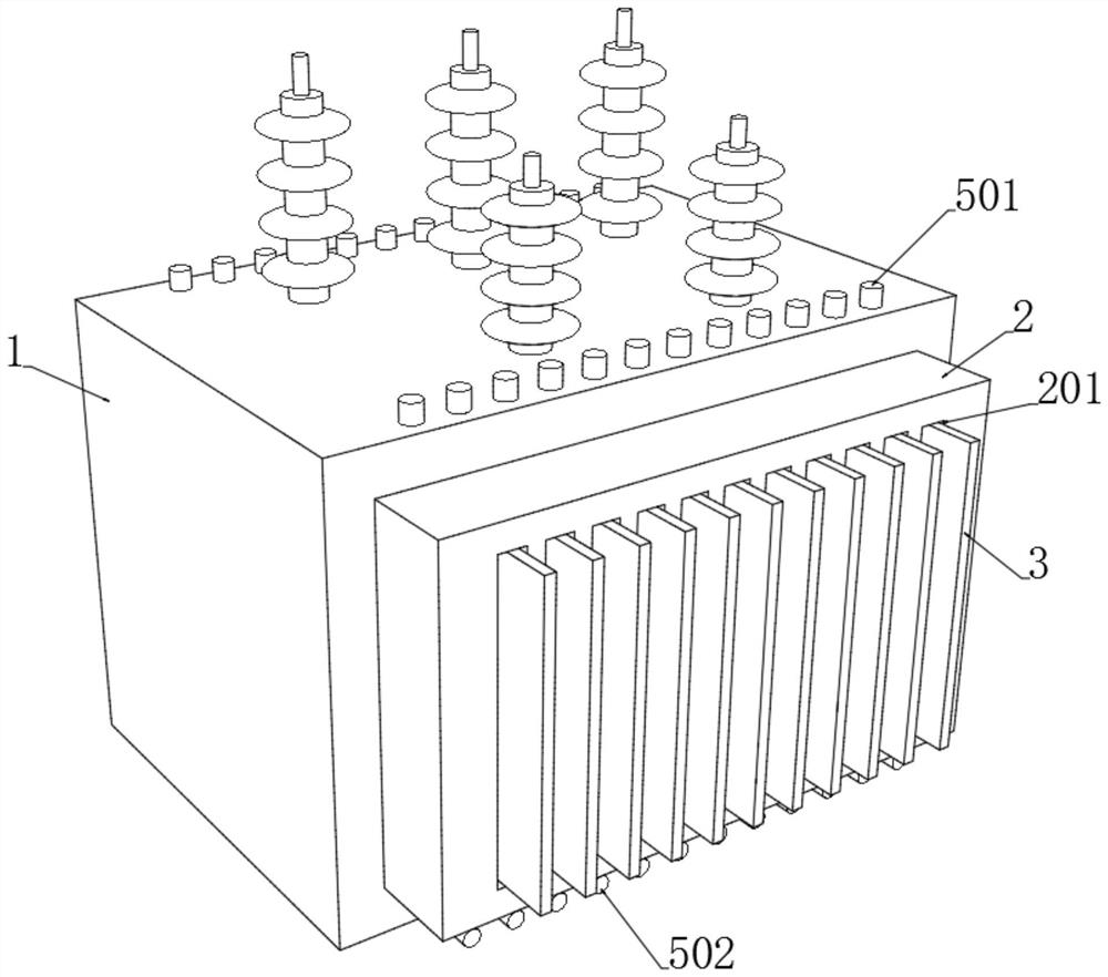
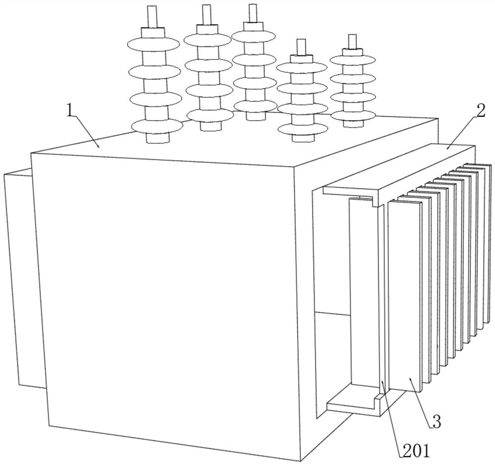
[0044] see Figure 1-3 , an overheating deformation ventilated transformer, comprising a transformer body 1, the left and right ends of the transformer body 1 are equipped with a heat dissipation shell 2 connected to the inside, and a plurality of heat dissipation chambers 201 are opened on the outer end wall of the heat dissipation shell 2, each heat dissipation chamber 201 is equipped with cooling fins 3 that run through the inside and outside. The upper and lower ends of the cooling fins 3 are respectively connected with the upper and lower inner walls of the cooling cavity 201, and the cooling fins 3 and the left and right walls of the cooling cavity 201 form ventilation gaps. The inner walls of the cooling shell 2 are fixedly connected. A heat conduction plate 6 spaced apart from a plurality of heat dissipation cavities 201, two adjacent heat conduction plates 6 are symmetrically arranged on the left and right sides of the heat sink 3, please refer to Figure 7-8 , the le...


PUM


Abstract

The invention discloses an overheating deformation ventilation type transformer, and belongs to the field of transformers. Radiating fins are additionally arranged at a plurality of radiating cavities formed in a radiating shell, and ventilation gaps are formed between the left ends and the right ends of the radiating fins and the radiating cavities; the inner wall of the heat dissipation shell is provided with a plurality of blocking pieces elastically buckled at the inner ends of the heat dissipation pieces, the blocking pieces block the inner sides of the ventilation gaps, when the interior of the transformer body is in a low-temperature normal state, the blocking pieces block the inner ends of the ventilation gaps one by one, the dustproof and moisture-proof effects are achieved under the condition that heat dissipation is not needed, and the service life of the transformer is prolonged. When the temperature in the transformer body gradually rises and reaches the deformation temperature of the thermal deformation part, the shape memory spring is straightened from an initial spring state and pushes the magnetic attraction plate to move towards one side of the blocking piece, the magnetic attraction plate plays a magnetic attraction role on the blocking piece, the blocking piece obliquely moves towards one side of the heat conduction plate, and at the moment, the blocking piece does not block the heat dissipation cavity any more; and the ventilation area is enlarged according to actual requirements, and the heat dissipation effect is improved.

Description

technical field [0001] The invention relates to the field of transformers, in particular to an overheating deformation ventilated transformer. Background technique [0002] The transformer is a complete set of voltage transformation equipment, which can be used for terminal power supply and ring network power supply. The conversion is very convenient, which ensures the reliability and flexibility of power supply. At present, with the development of voltage technology, the application of transformers tends to mature. However, when the transformer is working, a large amount of heat will be generated inside the transformer. If the internal heat of the transformer is too high, the internal components of the transformer will be burned, which is not conducive to the use of the transformer. [0003] At present, when the existing transformers dissipate heat, most of them dissipate heat through the cooling grooves opened on both sides or the heat sinks installed on the end wall of t...

Claims


Application Information

Patent Timeline
IPC IPC(8): H01F27/08H01F27/12H01F27/16H01F27/22H01F27/02
CPCH01F27/085H01F27/12H01F27/16H01F27/22H01F27/025
Inventor 王德彬
Owner 王德彬
Learn More