


Quick Research
Generate reliable direction feasibility study reports for your R&D in just a few steps.

Technical Q&A
Discover and master advanced knowledge NOW. Basics, ideas, possibilities, all at once.

Find Solutions
As an expert in R&D theories, this can generate solutions to your technical problems instantly.

Evaluate Feasibility
Analyze your overall solution with one click, know your potential R&D risks in advance.

Monitor Landscape
Get weekly tech updates, stay abreast of the latest tech innovations and key insights.
CO2 catalytic reduction device and application thereof
A catalyst, photoelectric catalysis technology, applied in the direction of electrode shape/type, cell, electrolysis process, etc., can solve the problems of good selectivity, difficulty in having a catalytic system at the same time, difficulty in recycling coenzymes, etc., and achieve the effect of slow reaction rate
- Summary
- Abstract
- Description
- Claims
- Application Information
AI Technical Summary
Problems solved by technology
Method used
Image

Examples
Embodiment 1
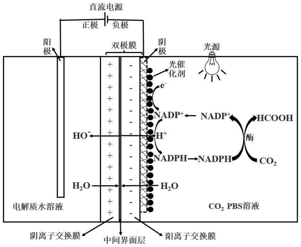
[0028] Such as figure 1 As shown, a CO 2 The catalytic reduction device comprises a reactor, a photoelectric catalytic composite membrane, a cathode, an anode, a DC power supply, and a light source; the photoelectric catalytic composite membrane is arranged in the reactor, and the reactor is divided into an anode chamber and a cathode chamber, and the anode and cathode respectively arranged in the anode chamber and the cathode chamber, the positive pole and the negative pole of the DC power supply are respectively connected to the anode and the cathode, and the light source is arranged above the cathode chamber;
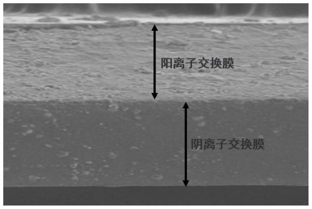
[0029] The photoelectrocatalytic composite membrane is composed of a bipolar membrane and a metal nickel mesh loaded with a photocatalyst on the surface, the bipolar membrane is composed of an anion exchange membrane and a cation exchange membrane, the metal nickel mesh is used as the cathode, and the platinum sheet is used as the anode. The metal nickel mesh with p...
Embodiment 2
[0040] The difference from Example 1 is that the preparation method of the photoelectrocatalytic composite film, the specific steps are as follows:
[0041] (1) Mix polyvinylpyrrolidone and quaternary ammonium polysulfone with a mass ratio of 2:1 and pour it into a beaker, add acetic acid aqueous solution with a mass fraction of 0.02%, stir continuously in a constant temperature water bath at 50°C, and add glutaraldehyde after completely dissolving , continue to stir for 1 hour, after static defoaming, cast on a flat and clean glass plate with a frame, put it into a blast drying oven to dry, and obtain an anion exchange membrane;
[0042] (2) Mix polyvinylpyrrolidone and sodium cellulose phosphate of equal mass and pour it into a beaker, add deionized water while stirring, heat to 60°C to dissolve, and add CaCl after it is completely dissolved 2 The solution was continuously stirred for 1 hour, and after standing for defoaming, it was cast on the surface of the anion exchange ...
Embodiment 3
[0046] The difference from Example 1 is that the preparation method of the photoelectrocatalytic composite film, the specific steps are as follows:
[0047] (1) Mix polyethylene benzyl chloride and polyimide with a mass ratio of 3:1 and pour it into a beaker, add an aqueous solution of acetic acid with a mass fraction of 0.03%, stir continuously in a constant temperature water bath at 60°C, and dissolve it completely Add glutaraldehyde, continue to stir for 1.5h, let it stand for degassing, cast it on a flat and clean glass plate with a frame, and put it into a blast drying oven to dry to obtain an anion exchange membrane;
[0048] (2) Mix polyphenylene ether and sodium cellulose sulfonate with equal mass and pour it into a beaker, add deionized water under stirring, heat to 70°C to dissolve, and add CaCl after it is completely dissolved 2 The solution was continuously stirred for 1 hour, and after standing for defoaming, it was cast on the surface of the anion exchange membra...
PUM
 Abstract
Description
Claims
Application Information
 - R&D Engineer
- R&D Manager
- IP Professional
- Industry Leading Data Capabilities
- Powerful AI technology
- Patent DNA Extraction
Browse by: Latest US Patents, China's latest patents, Technical Efficacy Thesaurus, Application Domain, Technology Topic, Popular Technical Reports.
© 2024 PatSnap. All rights reserved.Legal|Privacy policy|Modern Slavery Act Transparency Statement|Sitemap|About US| Contact US: help@patsnap.com