Cascade multi-level converter based on non-isolated back-to-back topology and control strategy thereof
A cascading multi-level and control strategy technology, which is applied in the direction of power transmission AC network, conversion of AC power input to AC power output, and conversion of AC power input to DC power output, etc., can solve the problem of increased volume and cost of flexible interface devices, Difficult distribution network large-scale application and other issues
- Summary
- Abstract
- Description
- Claims
- Application Information
AI Technical Summary
Problems solved by technology
Method used
Image
Examples
specific Embodiment 1
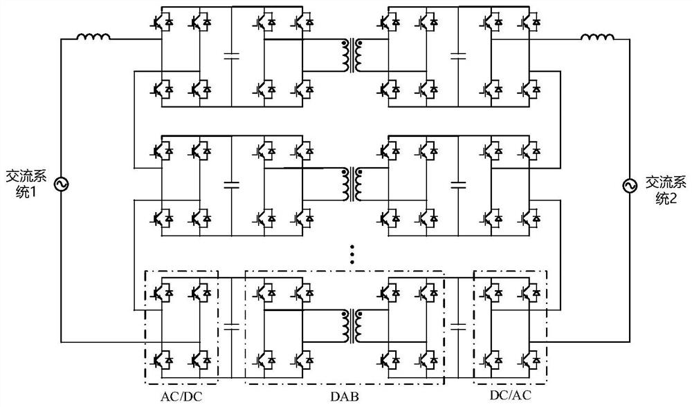
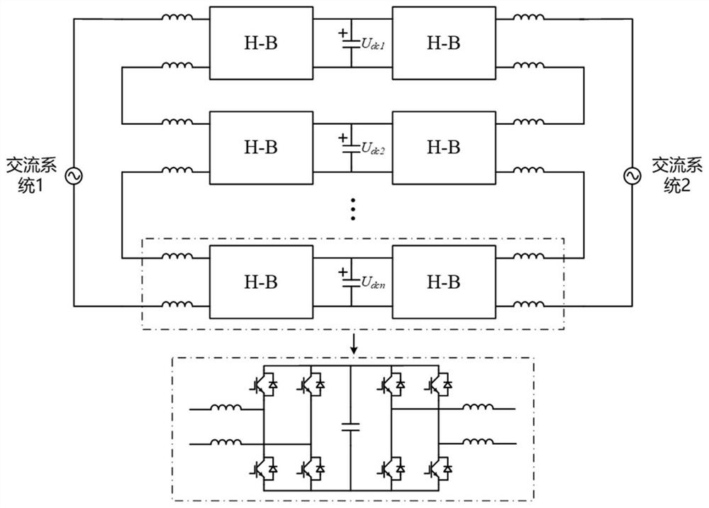
[0070] Set the simulation parameters of the system in Simulink / Matlab: the topology consists of three sub-modules, the inductance connected to the AC port of the H-bridge of the sub-modules is 0.5mH, and the capacitance of the DC side of the sub-modules is 1mF. The front end of the back-to-back converter is connected to an AC power supply, the input voltage is 3000V, and the rear end is connected to a resistive load with a resistance value of 55Ω.
[0071] In the simulation experiment of the embodiment of the present invention, the front-end converter adopts such as Figure 5 , Figure 6 The shown fixed UdcQ control strategy controls the total voltage of the DC side to 4500V, and the DC side voltage of each stage is 1500V. The back-end converter adopts such as Figure 8 The shown constant VF control controls the output voltage to 3300V. Simulation results such as Figure 9 , Figure 10 shown.
[0072] The simulation results show that the topology proposed by the embodime...
specific Embodiment 2
[0074] Set the simulation parameters of the system in Simulink / Matlab: the topology consists of three sub-modules, the inductance connected to the AC port of the H-bridge of the sub-modules is 0.5mH, and the capacitance of the DC side of the sub-modules is 1mF. The front end of the back-to-back converter is connected to AC system 1 with an input voltage of 3000V, and the rear end is connected to AC system 2 with an input voltage of 3000V.
[0075] In the simulation experiment of the embodiment of the present invention, the front-end converter adopts such as Figure 5 , Figure 6 The shown fixed UdcQ control strategy controls the total voltage of the DC side to 4500V, and the DC side voltage of each stage is 1500V. The back-end converter adopts such as Figure 8 As shown in the fixed PQ control, when the simulation starts, control active power P = 50kW, reactive power Q = -50kVar. At 0.5s, control active power P=50kW and reactive power Q=0Var. Simulation results such as F...
PUM
 Abstract
Description
Claims
Application Information
 - R&D
- Intellectual Property
- Life Sciences
- Materials
- Tech Scout
- Unparalleled Data Quality
- Higher Quality Content
- 60% Fewer Hallucinations
Browse by: Latest US Patents, China's latest patents, Technical Efficacy Thesaurus, Application Domain, Technology Topic, Popular Technical Reports.
© 2025 PatSnap. All rights reserved.Legal|Privacy policy|Modern Slavery Act Transparency Statement|Sitemap|About US| Contact US: help@patsnap.com


