


Quick Research
Generate reliable direction feasibility study reports for your R&D in just a few steps.

Technical Q&A
Discover and master advanced knowledge NOW. Basics, ideas, possibilities, all at once.

Find Solutions
As an expert in R&D theories, this can generate solutions to your technical problems instantly.

Evaluate Feasibility
Analyze your overall solution with one click, know your potential R&D risks in advance.

Monitor Landscape
Get weekly tech updates, stay abreast of the latest tech innovations and key insights.
Crushing pulverizer
A technology of a pulverizer and a crushing mechanism, which is applied in the direction of grain processing, etc., and can solve the problems of inability to crush minerals, large volume, unfavorable crushing and rolling, etc., to ensure crushing efficiency and processing accuracy, improve processing efficiency, and increase stability Effect
- Summary
- Abstract
- Description
- Claims
- Application Information
AI Technical Summary
Problems solved by technology
Method used
Image

Examples
Embodiment 1
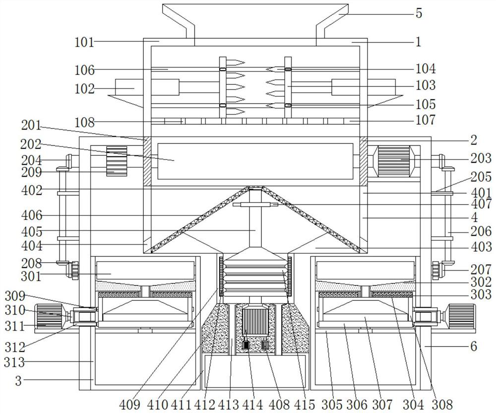
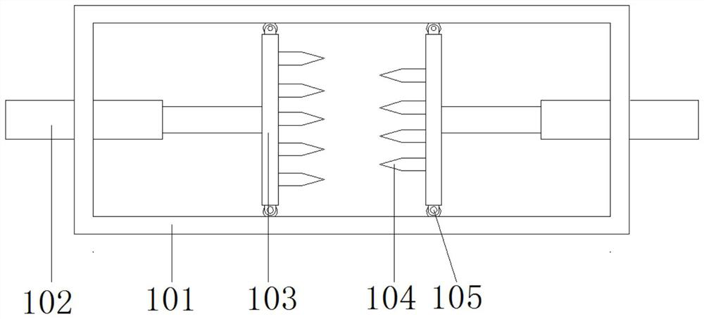
[0032] see Figure 1-2 , a crushing pulverizer, including a crushing mechanism 1 and a bending support plate 6, the crushing mechanism 1 includes a first frame 101, a telescopic rod 102, a moving plate 103, crushing teeth 104, moving wheels 105, chute 106, sieve plate 107 and the through hole 108; the top of the first frame 101 is fixedly installed with the feeding hopper 5; the left and right ends of the first frame 101 are fixedly installed with a telescopic rod 102, and one end of the telescopic rod 102 is fixedly connected with a moving plate 103, and the moving plate 103 One side of the first frame 101 is fixedly connected with crushing teeth 104; the inner bottom end of the first frame 101 is fixedly connected with a sieve plate 107, and the interior of the sieve plate 107 is provided with a through hole 108.
[0033] Further, moving wheels 105 are fixedly installed on the front and rear sides of the moving plate 103 , and sliding grooves 106 are provided on the front an...
Embodiment 2
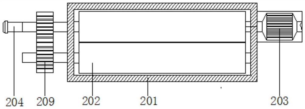
[0036] see figure 1 , image 3 and Figure 4, a crushing mechanism 2 is arranged below the first frame 101, and the crushing mechanism 2 includes a second frame 201, a first crushing roller 202, a biaxial motor 203, a first bevel tooth 204, a connecting plate 205, a connecting gear rod 206, a second Bevel teeth 207 and gears 208; a second frame 201 is fixedly connected to the bottom of the first frame 101, and a first crushing roller 202 is rotatably connected to the inside of the second frame 201. Second gears 209 are fixedly connected to the left ends of the two sets of first crushing rollers 202, and the two sets of second gears 209 are geared and connected; the right ends of the first crushing rollers 202 on the rear side are fixedly connected with a biaxial motor 203, and the biaxial motor 203 is fixed Installed on the outer wall of the second frame 201 . One end of the biaxial motor 203 and the second gear 209 on the rear side are fixedly connected to the first bevel ...
Embodiment 3
[0041] see figure 1 and Figure 5 , a second grinding mechanism 4 is arranged below the second frame 201, and the second grinding mechanism 4 includes a third frame 401, a limit groove 402, a triangular spacer 403, a discharge hole 404, a rotating shaft 405, and a conical filter screen 406 , vibrating plate 407, micro stepping motor 408, cylinder 409, fixed table 410, storage box 411, second grinding ring 412, material guide tube 413, second motor 414 and second grinding table 415; second frame The bottom of 201 is fixedly connected with a third frame 401, the inner wall of the third frame 401 is fixedly connected with a conical filter screen 406, the inner bottom end of the conical filter screen 406 is fixedly connected with a triangular spacer 403, and the triangular spacer 403 is fixedly connected to On the inner wall of the third frame 401, a cylinder 409 is fixedly connected to the bottom of the triangular spacer 403, a fixing table 410 is fixedly connected to the bottom...
PUM
 Abstract
Description
Claims
Application Information
 - R&D Engineer
- R&D Manager
- IP Professional
- Industry Leading Data Capabilities
- Powerful AI technology
- Patent DNA Extraction
Browse by: Latest US Patents, China's latest patents, Technical Efficacy Thesaurus, Application Domain, Technology Topic, Popular Technical Reports.
© 2024 PatSnap. All rights reserved.Legal|Privacy policy|Modern Slavery Act Transparency Statement|Sitemap|About US| Contact US: help@patsnap.com