Eureka AIR delivers breakthrough ideas for toughest innovation challenges, trusted by R&D personnel around the world.

Lithography machine energy detection device and detection method

A technology of energy detection and lithography machine, which is applied in the direction of using electric radiation detectors for photometry, etc., can solve the problems of regional non-compliance, substrate property loss, pass rate attenuation, etc., to improve exposure accuracy, increase energy range, Effect of Preventing Measurement Errors

Pending Publication Date: 2022-04-12
锡凡半导体无锡有限公司
View PDF3 Cites 0 Cited by
  • Summary
  • Abstract
  • Description
  • Claims
  • Application Information

AI Technical Summary

Problems solved by technology

[0002] Lithography machine, also known as exposure machine, exposure system, lithography system, etc., is the core device for manufacturing chips. It draws graphics on the substrate by controlling light. In the process of drawing graphics, the uniformity of light intensity will affect the later process. The etching effect in the lithography machine will affect the lithography accuracy of the lithography machine, and the price of the substrate is relatively expensive, and the scrapping of the substrate will cause large property losses. Therefore, it is necessary to detect the light uniformity of the lithography machine
[0003] The existing lithography machine energy detection device mainly detects the uniformity through the energy probe. There may be regional substandard light output, which will affect the exposure effect of the lithography machine, which will lead to an increase in the probability of substrate scrapping; and the maximum gray value of the CCD spot is 255. When the spot is too bright, the gray value of the CCD will If it is greater than 255, the CCD will appear oversaturation cut-off phenomenon; the driving mechanism of the existing lithography machine energy detection device is mostly the direct drive of the screw rod with the servo motor or the linear motor. These two methods are heavy and will cause movement. There will be a large deformation at the energy detection device in the mechanism, which will affect the accuracy of the lithography machine, and the attenuation sheet will have attenuation of the pass rate under the irradiation of strong light

Method used

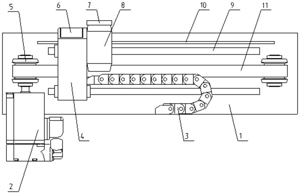
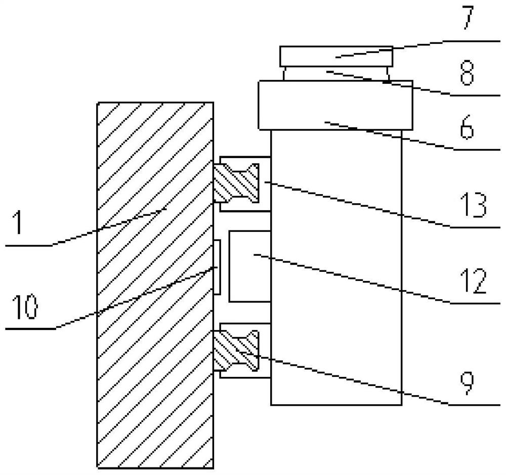

Image

  • Lithography machine energy detection device and detection method
  • Lithography machine energy detection device and detection method

Examples


Embodiment 1

[0031] see figure 1 and figure 2 , the lithography machine energy detection device proposed by the present invention includes a mounting plate 1, the mounting plate 1 is fixedly installed in the movement mechanism of the lithography machine, and two guide rails 9 are fixedly arranged on the front end of the mounting plate 1 in a transverse direction, so that One side of the mounting plate is fixedly provided with a servo motor 2, the servo motor 2 drives the mounting seat 4 through the synchronous wheel 5 and the synchronous belt 11, and the mounting seat 4 is slidably arranged between two guide rails through the slider 13. The servo motor 2 is the engine that controls the operation of the mechanical components in the servo system. It is an auxiliary motor indirect transmission device that can control the speed and the position accuracy is very accurate. It can convert the voltage signal into torque and speed to drive the mounting seat 4.

[0032] A CCD 8 is fixedly installe...

Embodiment 2

[0040] In this embodiment, the present invention also proposes a method for detecting the energy of a lithography machine, comprising the following steps:

[0041] Step 1: Divide the light-emitting area of ​​the lithography machine into N equal parts according to the field of view of the CCD, and the number of CCD-sensitive pixels is M when the light-emitting area of ​​each part of the lithography machine is projected separately;

[0042] Step 2: Move the CCD to the light-emitting area of ​​the lithography machine by controlling the movement mechanism of the lithography machine and the servo motor that drives the mounting seat to slide, respectively measure the gray value of each pixel in each area, and calculate the average to obtain Ambient light gray value B;

[0043] Step 3: Map separately the light-emitting areas of the N lithography machines after equal division in turn, and use the CCD to measure the gray value of each pixel in the area, and obtain all the light-emittin...


PUM


Abstract

The invention belongs to the field of energy detection, and discloses a photoetching machine energy detection device and method, the device comprises a mounting plate, the mounting plate is fixedly mounted in a photoetching machine movement mechanism, two guide rails are transversely and fixedly arranged on the front end face of the mounting plate, and a servo motor is fixedly arranged on one side of the mounting plate; the servo motor drives a mounting base through a synchronous wheel and a synchronous belt, and the mounting base is arranged between the two guide rails in a sliding mode through a sliding block. Through cooperative use of the CCD and the energy probe, energy detection which is accurate to a pixel point is carried out on the emergent light of the photoetching machine, so that more accurate detection on the emergent light energy uniformity of the photoetching machine is facilitated, the exposure precision of the photoetching machine is effectively improved, and a measurement error caused by aging of an attenuation sheet is prevented; through the use of the attenuation sheet, the detectable energy range of the CCD is effectively improved, through the use of the synchronous belt, the weight of the energy detection device is effectively reduced, and the deformation of a motion mechanism is effectively reduced.

Description

technical field [0001] The invention belongs to the technical field of energy detection, and in particular relates to an energy detection device and a detection method for a photolithography machine. Background technique [0002] Lithography machine, also known as exposure machine, exposure system, lithography system, etc., is the core device for manufacturing chips. It draws graphics on the substrate by controlling light. In the process of drawing graphics, the uniformity of light intensity will affect the later process. The etching effect in the lithography machine will affect the lithography accuracy of the lithography machine, and the price of the substrate is relatively expensive, and the scrapping of the substrate will cause large property losses. Therefore, it is necessary to detect the light uniformity of the lithography machine. [0003] The existing lithography machine energy detection device mainly detects the uniformity through the energy probe. There may be reg...

Claims


Application Information

Patent Timeline
Patent Type & Authority Applications(China)
IPC IPC(8): G01J1/42
Inventor 霍大云刘麟跃刘靖
Owner 锡凡半导体无锡有限公司
Why Eureka
Eureka Blog
Learn More