
Water stop device for preventing water leakage of through hole and processing method thereof

A technology of a water-stop device and a processing method, which is applied to vertical shaft equipment, earth-moving drilling, wellbore lining, etc., can solve the problems of difficult to control the flow direction of the slurry, fracture of the water-stop ring weld, poor sealing effect, etc., and achieves simple installation. , not easy to dislocate, good sealing effect

Pending Publication Date: 2022-04-12
BEIJING CHINA COAL MINE ENG CO LTD
View PDF0 Cites 0 Cited by
  • Summary
  • Abstract
  • Description
  • Claims
  • Application Information

AI Technical Summary

Problems solved by technology

However, the orifice pipe cannot be installed at the junction of the through hole and the auxiliary surface segment, and it is difficult to control the flow direction of the grout through the grouting hole of the segment, and the plugging effect is not good
Welding the water-stop ring in the middle of the freezing pipe can seal the gap, but during the freezing process, the water-stop ring welding seam is prone to fracture when it is frozen, resulting in broken pipe accidents in the freezing pipe

Method used


Image

  • Water stop device for preventing water leakage of through hole and processing method thereof
  • Water stop device for preventing water leakage of through hole and processing method thereof
  • Water stop device for preventing water leakage of through hole and processing method thereof

Examples


Embodiment 1

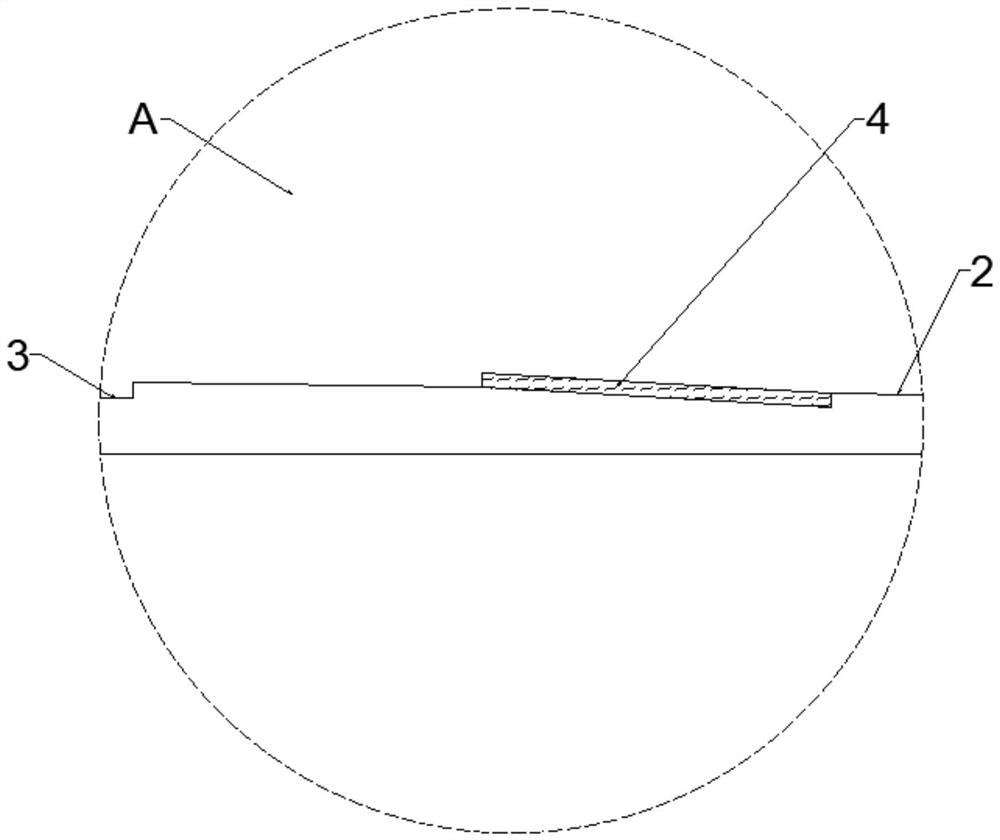
[0038]In this embodiment, the water stop device used to prevent water leakage through the through hole is as follows: figure 1 and figure 2 As shown, it includes a water-tight water-stop body 6 and a water-sealing rubber ring 4; One section; along the outer surface of the self-tightening water-stop section 2 of the water-leakage water-stop body 6, a card groove 5 is provided in the circumferential direction, and the water-sealing rubber ring 4 is set on the water-leakage water-stop body 6 through the card groove 5, and the water-leakage water-stop body 6 One end is detachably and fixedly connected with the drill bit, and the other end is detachably and hermetically fixedly connected with the freezing tube. The length of the water leakage and water stop body 6 is 1.5m, and the inner diameter is 73mm.

[0039] Such as Figure 5 As shown, the leakage and water-stop body 6 is composed of the drill bit connection section 1, the self-tightening water-stop section 2 and the freez...

Embodiment 2

[0044] The processing method of the water stop device for preventing through-hole water leakage in embodiment 1 comprises the following steps:

[0045] Step A: Take a 95*11mm seamless steel pipe with a length of 1.5m, and use a lathe to process the seamless steel pipe into a leaky waterstop body 6, so that the leaky waterstop body 6 is a self-tightening waterstop section with thick ends and thin ends. Seam steel pipe, that is, use a lathe to process the outer diameter of the seamless steel pipe at a distance of 0-0.5m from the first end to 89mm, and at the same time process the inner diameter according to the size of the check valve and the drill bit and turn the thread to complete the drill bit connection section 1 processing; then the outer diameter of the seamless steel pipe 0.5-0.65m from the first end is processed into a self-tightening water-stop section 2 with a diameter increasing from 89mm to 93.5mm; then the remaining part of the seamless steel pipe is The outer diam...


PUM

PropertyMeasurementUnit
lengthaaaaaaaaaa
diameteraaaaaaaaaa
thicknessaaaaaaaaaa

Abstract

The invention discloses a water stopping device for preventing water leakage of a through hole and a machining method of the water stopping device. The device comprises a water leakage stopping body and a water sealing rubber ring. The water leakage and stop body is a seamless steel tube with a thick self-tightening water stop section and two thin ends, the self-tightening water stop section is a section on the water leakage and stop body, and the water sealing rubber ring is sleeved on the self-tightening water stop section of the water leakage and stop body; one end of the water leakage stopping body is detachably and fixedly connected with the drill bit, and the other end of the water leakage stopping body is detachably and fixedly connected with the freezing pipe in a sealed mode. The machining method of the device comprises the steps that a lathe is adopted for machining the water leakage and stop body, then the water sealing rubber ring is customized, and finally the water sealing rubber ring is installed on the water leakage and stop body. The self-tightening device for preventing the through hole from leaking water is designed for solving the problems that the frozen through hole is prone to leaking water and gushing sand and the like, and after the self-tightening device is installed, the gap of the combination portion of the through hole and the pipe piece can be thoroughly plugged only by controlling the drilling length of a drilling machine.

Description

technical field [0001] The invention relates to the technical field of water leakage and stoppage through holes. Specifically, it is a water stop device for preventing water leakage through holes and a processing method thereof. Background technique [0002] In the construction of the subway communication channel, in order to facilitate the operation monitoring of the refrigeration station and save engineering costs, the refrigeration station is usually only built in the tunnel on one side, and the refrigerant required for the freezing hole on the secondary side is transported through the through hole. [0003] In the process of through-hole construction, the orifice pipe is usually installed at the opening position of the main surface and grouted through the orifice pipe to prevent water penetration and sand gushing at the junction of the frozen pipe and the segment. However, the orifice pipe cannot be installed at the junction of the through hole and the sub-surface segme...

Claims


Application Information

Patent Timeline
Patent Type & Authority Applications(China)
IPC IPC(8): E21D11/38B23P15/00
Inventor 高伟彭飞李宁韩玉福刘明亮杨阳杨志刚张富健陈红蕾孔令辉付财许舒荣叶玉西宁方波张洪波王康丁少令
Owner BEIJING CHINA COAL MINE ENG CO LTD
Learn More