Optical flow control device based on surface lattice resonance and application thereof
An optofluidics and device technology, applied in the field of optofluidics, can solve the problems of low light absorption rate and low fluid convection speed, and achieve the effects of high absorption, strong local electromagnetic field, and fast fluid convection
- Summary
- Abstract
- Description
- Claims
- Application Information
AI Technical Summary
Problems solved by technology
Method used
Image
Examples
Embodiment 1
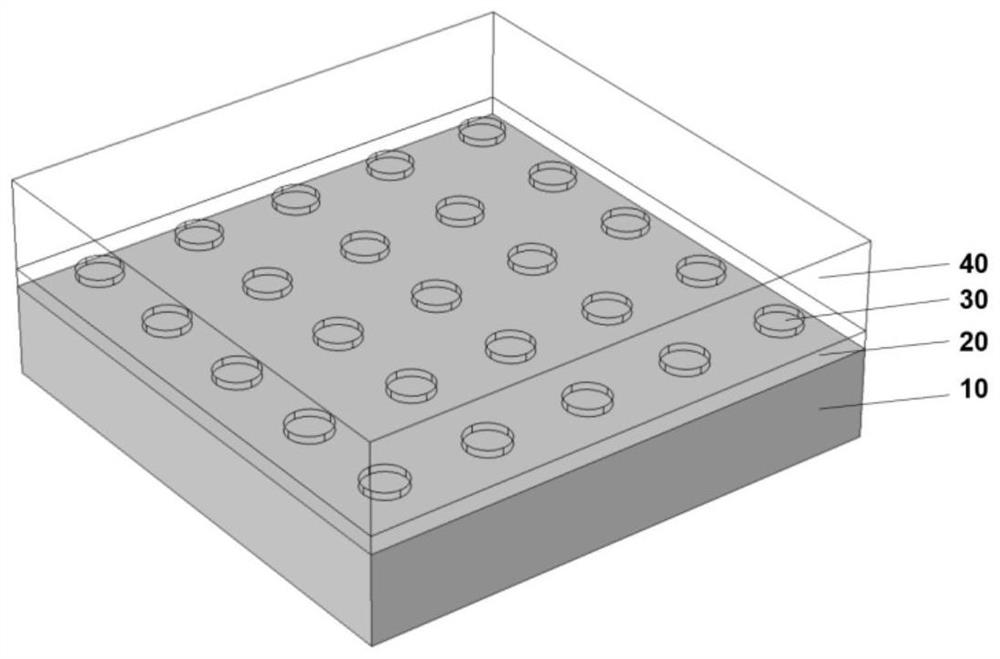
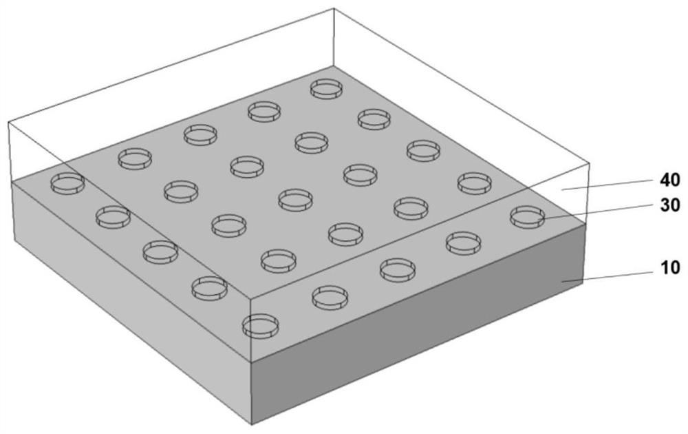
[0036] figure 1 A schematic structural diagram of an optofluidic device based on surface lattice resonance provided by the present invention, the structure includes a substrate layer, a thin film layer, a periodic nanostructure layer, and a liquid environment layer. Wherein the film layer is arranged on the substrate layer, and the unit structure of the periodic nanostructure is a disc, which is arranged on the film layer. A layer of liquid environment is located above the layer of periodic nanostructures.
[0037] in particular:
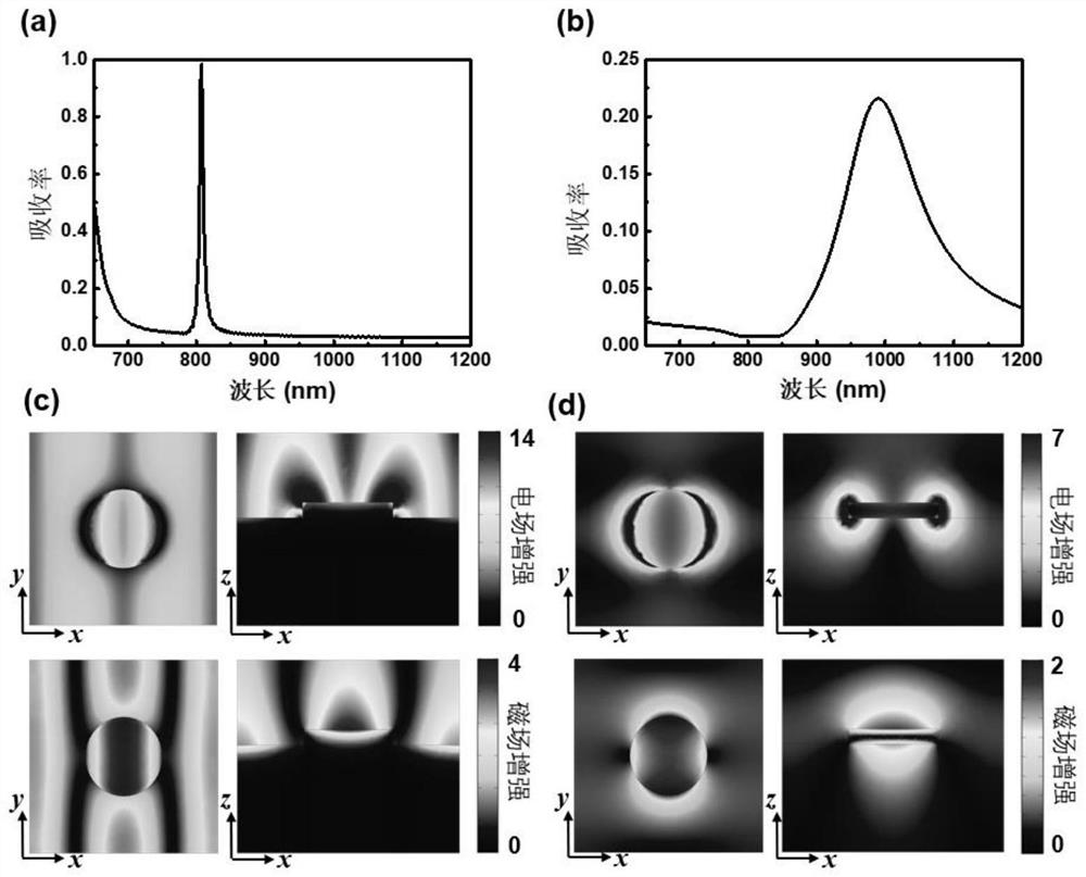
[0038] The electromagnetic, photothermal and fluid responses of the optofluidic device based on surface lattice resonance in this embodiment are as follows:
[0039] By using the three-dimensional finite element method FEM calculation software COMSOL Multiphysics to conduct calculation simulations and experiments, multidisciplinary problems including optics, thermodynamics and fluid dynamics are studied. The specific parameters are optimized as fo...
Embodiment 2
[0047] Based on Embodiment 1, the embodiment of the present application provides another optofluidic device based on surface lattice resonance. Such as Figure 7 As shown, it is basically the same as in Example 1, the only difference is that the periodic nanostructure is a square nanodisk. Preferably, the nano square disk has a side length of 240nm and a thickness of 40nm.
[0048] Figure 8 , Figure 9 with Figure 10 They are the absorption spectrum, electromagnetic field distribution, light-induced temperature increase distribution, and heat-induced fluid convection distribution diagrams of an optofluidic device based on surface lattice resonance in Example 2 of the present invention, from Figure 8 , Figure 9 with Figure 10 It can be seen that without changing the resonance, the square disk increases the area of the metal nanostructure relative to the disk, thereby increasing the photothermal response of the optofluidic device, that is, the heat generated, thereb...
Embodiment 3
[0050] Based on the surface lattice resonance-based optofluidic device disclosed in Examples 1 and 2, this embodiment discloses an application of a surface lattice resonance-based optofluidic device in disease diagnosis and treatment, which specifically includes the following steps:
[0051] Step 1, placing the optofluidic device based on surface lattice resonance in a microfluidic chamber in a liquid environment;
[0052] Step 2, mixing antigen-modified small-sized nanostructures into the microfluidic chamber, and labeling these beads with fluorescence;
[0053] Step 3, mixing the antibody-modified large-scale nanostructures into the microfluidic chamber;
[0054] Step 4, irradiating the optofluidic device with laser light to generate fluid convection in the microfluidic chamber;
[0055] Step 5, the antigen-modified fluorescently labeled nanostructures collide with the antibody-modified nanostructures under the action of convection and fully carry out the antigen-antibody r...
PUM
| Property | Measurement | Unit |
|---|---|---|
| radius | aaaaa | aaaaa |
| thickness | aaaaa | aaaaa |
| length | aaaaa | aaaaa |
Abstract
Description
Claims
Application Information
 - Generate Ideas
- Intellectual Property
- Life Sciences
- Materials
- Tech Scout
- Unparalleled Data Quality
- Higher Quality Content
- 60% Fewer Hallucinations
Browse by: Latest US Patents, China's latest patents, Technical Efficacy Thesaurus, Application Domain, Technology Topic, Popular Technical Reports.
© 2025 PatSnap. All rights reserved.Legal|Privacy policy|Modern Slavery Act Transparency Statement|Sitemap|About US| Contact US: help@patsnap.com


