Automatic cutting machine for net film

A cutting machine, automatic technology, applied in the direction of cleaning method using gas flow, winding strips, sending objects, etc., can solve the problems of difficult cutting dust, uncut, film pushing, etc., to reduce manpower input and speed up Improvement of process time and stability

Pending Publication Date: 2022-04-08
昆山仕弗达自动化科技有限公司
View PDF0 Cites 0 Cited by
  • Summary
  • Abstract
  • Description
  • Claims
  • Application Information

AI Technical Summary

Problems solved by technology

[0002] Water treatment membranes are usually used to filter impurities in water. Its production is usually made of composite spot welding of various membranes, including omentum and st membrane, etc., and the omentum needs to be pulled out twice as much as the ST membrane, and the net The film is folded, and the ST film is placed between the folded omentum, and then followed by spot welding. In the existing equipment, there are the following problems: 1. The edge of the raw material of the omentum is irregular and needs to be cut. Due to the material of the film itself The problem is that a lot of dust will be generated during cutting, and the existing treatment method is to set a suction pipe on the edge to suck out the material generated at the edge, but the installation of the suction pipe needs support, and it is difficult to install in some small spaces. The position of the air duct is not aligned, and it is difficult to absorb cutting dust. 2. Most of the existing equipment is cut and removed manually, which consumes manpower and has a low degree of automation. 3. Due to the different materials of different films, it is difficult to When the filter membrane is soft, use a cutter to cut it. If the sharpness of the cutter decreases, it is easy to push the membrane without being cut

Method used


Image

  • Automatic cutting machine for net film
  • Automatic cutting machine for net film
  • Automatic cutting machine for net film

Examples


Embodiment Construction

[0025] The technical solutions in the embodiments of the present invention will be apparent from the drawings in the embodiment of the present invention.

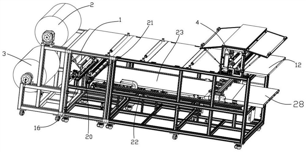
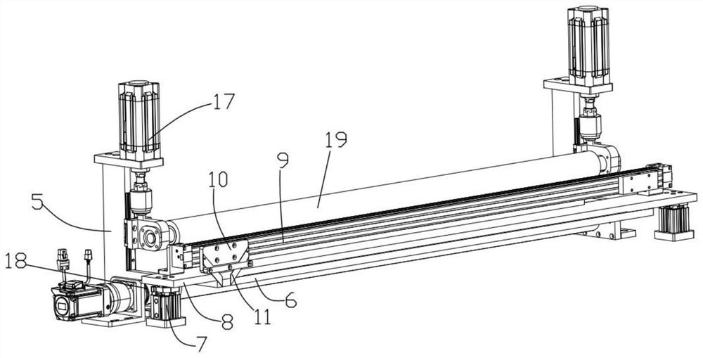
[0026] Such as figure 1 As shown, the present invention proposes a retinal automatic cutting machine including upper brackets 1 and a lower bracket 16, and the upper bracket 1 is provided with a first film roller 2 and a pulling a weapon assembly 4, such as figure 2 As shown, the pulled cutting assembly 4 includes a first rack 5, and a pull film mechanism is provided on one side of the pulled membrane mechanism, a first film roller. 2 Used to place the ST film, the second membrane roller 3 of the lower bracket 16 is used to place the retina, the first film roller 2 and the second film roller 3 are respectively provided with a counter, for calculating the first film roller 2 and The length of the material discharged from the second film roller 3;

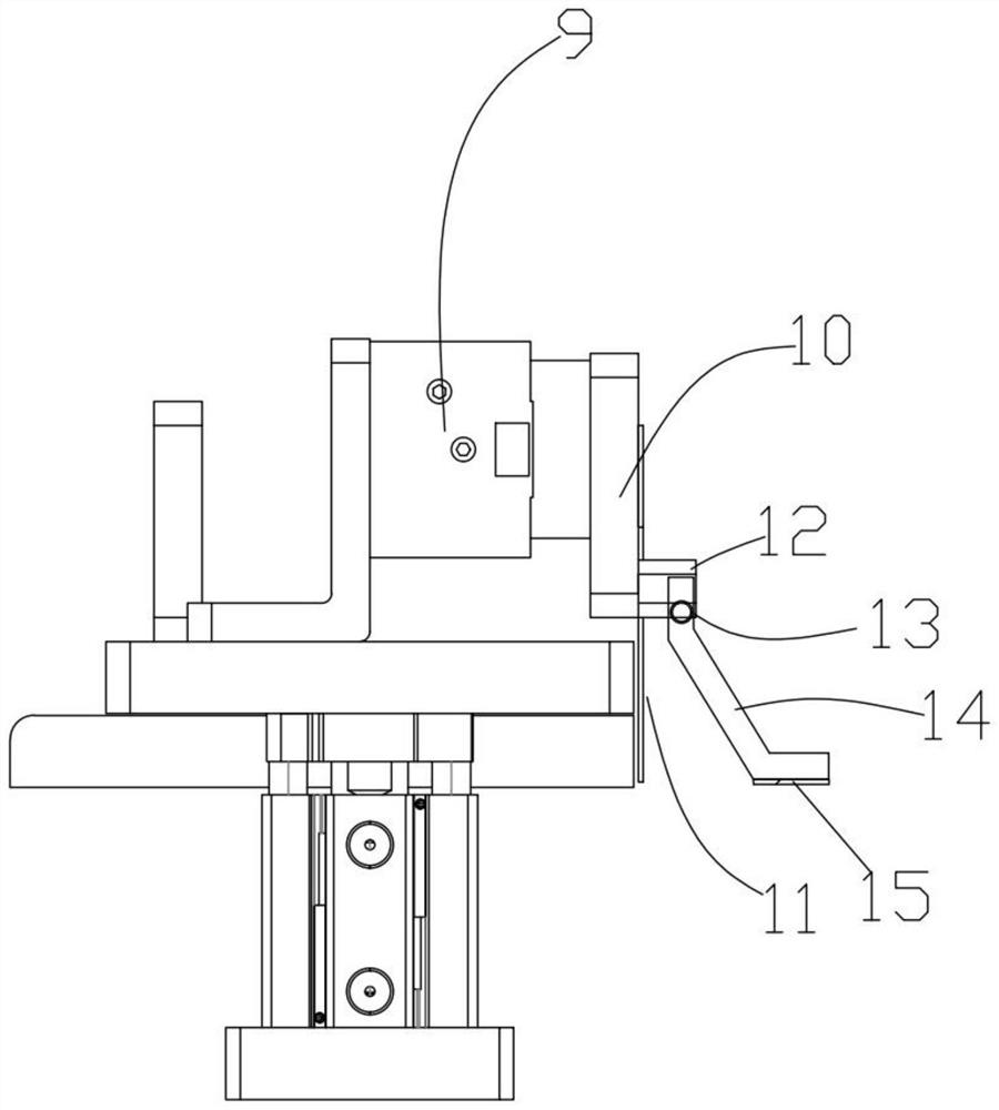
[0027] The first cutting mechanism includes a carrier plate 6, and the carrier pl...


PUM


Abstract

The invention provides an automatic net film cutting machine which comprises an upper support and a lower support, a first film roller and a pulling film cutting assembly are arranged at the two ends of the upper support, the pulling film cutting assembly comprises a first vertical frame, a film pulling mechanism is arranged on the first vertical frame, and a first film cutting mechanism is arranged on one side of the film pulling mechanism; the first film cutting mechanism comprises a bearing plate, first jacking air cylinders are arranged at the two ends of the bearing plate, the output ends of the first jacking air cylinders are connected with a first pressing plate, the first pressing plate is located above the bearing plate, a first module is arranged on the first pressing plate, and a first cutter block is connected to the first module. The cutting machine is provided with the self-dust-suction waste roller, dust can be sucked away in time when waste is cut, the occupied area is small, when a net film is cut, a pressing tensioning mechanism is particularly arranged, the surface of a die body is effectively tensioned, the cutting stability of the soft net film is greatly improved, the automatic folding function is finally set, manpower input is reduced, and the follow-up process time is shortened.

Description

Technical field [0001] The present invention relates to the field of water treatment membrane supporting equipment, in particular to a reticular automatic cutting machine. Background technique [0002] The water treatment membrane is usually used for the impurities in filtration, which is usually welded by a plurality of membrane composite points, including a reticulum and a ST film, etc. The membrane is folded, and the ST film is placed between the folded reticulum, and then welded by subsequent point, existing equipment, the following problems: 1, the edge of the raw material of the reticulum has a shaped, needed, due to the material itself The problem, when cutting, a large amount of dust is generated, while the existing processing method is to absorb the material generated by the suction tube at the edge, but the suction pipe is installed, in some small space, it is difficult to install, suck Dust position is not aligned, it is difficult to adsorb cut dust, 2, most of the exi...

Claims


Application Information

Patent Timeline
IPC IPC(8): B65H35/06B65H23/26B08B5/04B08B13/00
Inventor 姚昌吉
Owner 昆山仕弗达自动化科技有限公司
Why Eureka
Try Eureka