
Industrial water chilling unit

A chiller and industrial technology, applied in the direction of gravity filter, fixed element filter, filter separation, etc., can solve the problems of increased maintenance cost, blockage of cooling water circulation loop, no filter device, etc., to increase the contact area, Enhance the cleaning effect and ensure the sealing effect

Pending Publication Date: 2022-04-08
陈中浩
View PDF0 Cites 0 Cited by
  • Summary
  • Abstract
  • Description
  • Claims
  • Application Information

AI Technical Summary

Problems solved by technology

[0005] The purpose of the present invention is to provide an industrial chiller. The specific problem to be solved by the present invention is that the existing air-cooled chiller does not have a filter device, and usually unfiltered water enters the chiller, which may cause blockage of the cooling water circulation circuit. At the same time, impurities entering the chiller will cause wear of various parts and pipes in the water circulation system, reducing service life and increasing maintenance costs

Method used

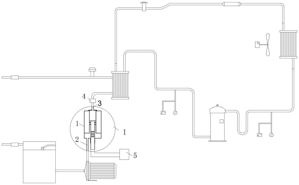

Image

  • Industrial water chilling unit
  • Industrial water chilling unit
  • Industrial water chilling unit

Examples


Embodiment approach

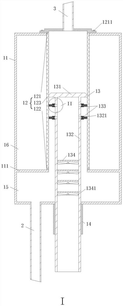
[0030] As an embodiment of the present invention, there is a protruding sleeve 14 under the housing 11, the inner wall of the sleeve 14 is in sliding and sealing connection with the outer wall of the ejector rod 132, and the retaining ring 111 and the bottom of the housing 11 form a stock solution chamber 15 , the outer side of the filter screen 123 and the inner wall of the housing 11 constitute the filtrate chamber 16 .

[0031] There is a raised sleeve 14 under the shell 11, and the top column 13 reciprocates up and down along the sleeve 14, which increases the contact area between the top column 13 and the sleeve 14, improves the guiding effect and ensures the sealing effect at the same time, the sleeve 14 The inner wall is in sliding and sealed connection with the outer wall of the push rod 132, and the unfiltered water enters the raw liquid chamber 15 through the water inlet 2, and then enters the lower part of the filter screen 123 along the area between the filter scree...


PUM


Abstract

The invention belongs to the technical field of water chilling machines, and particularly relates to an industrial water chilling unit which comprises a purification device, a water inlet, a water outlet and a gas-liquid separator, the water inlet is located in the lower left end of the purification device, the water outlet is located in the center of the top of the purification device, and the purification device comprises a shell, a filter element device and a top column; the baffle ring is located on the lower half portion of the shell, the filter element device is installed above the baffle ring and comprises an upper cover plate, a lower cover plate and a filter screen, the upper cover plate is fixedly connected with the filter screen, the filter screen is fixedly connected with the lower cover plate, the top column is vertically installed in the filter screen and comprises a top plate and a top rod, and the top plate is in sliding connection with the inner side of the filter screen. According to the invention, the air pump is directly used as a power source, the structure is relatively simple, the cost of later maintenance is reduced, secondary filtration is realized through the design of the top column, and the filtration effect is improved.

Description

technical field [0001] The invention belongs to the technical field of chillers, and in particular relates to an industrial chiller. Background technique [0002] The working principle of industrial chillers is vapor compression refrigeration, which uses the principle of heat absorption when liquid refrigerant vaporizes and heat release when steam condenses. Industrial chillers can provide chilled water with constant temperature, constant flow and constant pressure. During the operation of the ultraviolet laser chiller, a certain amount of water can be injected into the internal water tank of the machine, the water is cooled by the chiller refrigeration system, and then the water pump injects the low-temperature frozen water into the equipment that needs to be cooled, and the frozen water will be The heat inside the machine is taken away, and the high-temperature hot water is returned to the water tank to cool down again, so that the cooling is circulated and exchanged to a...

Claims


Application Information

Patent Timeline
Patent Type & Authority Applications(China)
IPC IPC(8): B01D29/31B01D29/56B01D29/64B01D29/66B01D19/00
Inventor 陈中浩邢刚
Owner 陈中浩
Learn More