Steel bar bending equipment for construction

A kind of equipment and steel bar technology, which is applied in the field of steel bar bending equipment, can solve problems such as difficult handling or pushing, safety hazards, and steel bar ejection, and achieve the effects of reducing work burden, ensuring safety, and facilitating handling and pushing

Inactive Publication Date: 2022-04-05
湖南凡工建筑工程有限公司
View PDF0 Cites 0 Cited by
  • Summary
  • Abstract
  • Description
  • Claims
  • Application Information

AI Technical Summary

Problems solved by technology

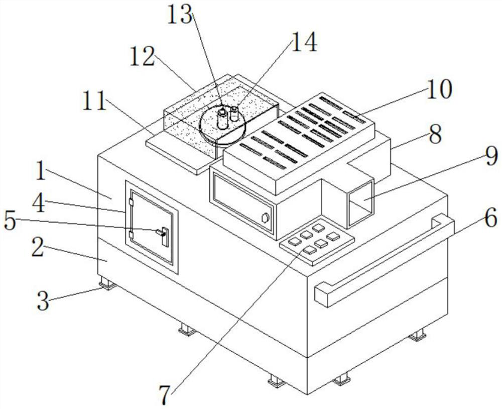
[0005] The purpose of the present invention is to provide a steel bar bending equipment for construction, to solve the single design of the current steel bar bending device proposed in the above background technology, requiring workers to manually put the steel bar into the steel bar bending device for bending, this method exists It is a great safety hazard. If the operation is not done properly, the staff will be easily injured and accidents will occur. There is also a hidden danger that the steel bar will pop out from the bending device during bending, and the existing steel bar bending device cannot automatically transport the steel bar into the steel bar for bending. Automatic bending is carried out in the device, and most of the steel bending devices are too heavy and difficult to carry or push

Method used


Image

  • Steel bar bending equipment for construction
  • Steel bar bending equipment for construction
  • Steel bar bending equipment for construction

Examples


Embodiment Construction

[0026] The following will clearly and completely describe the technical solutions in the embodiments of the present invention with reference to the accompanying drawings in the embodiments of the present invention. Obviously, the described embodiments are only some, not all, embodiments of the present invention. Based on the embodiments of the present invention, all other embodiments obtained by persons of ordinary skill in the art without making creative efforts belong to the protection scope of the present invention.

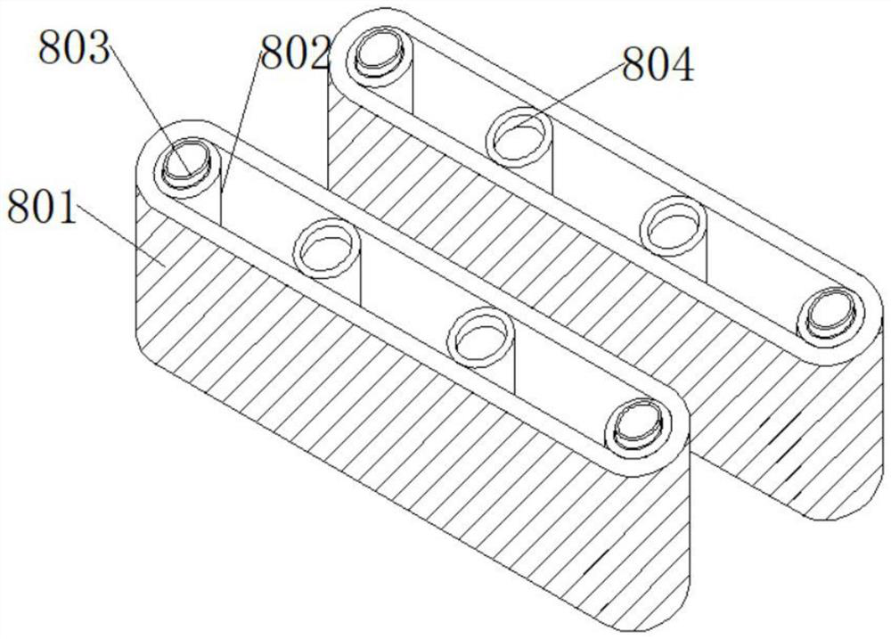
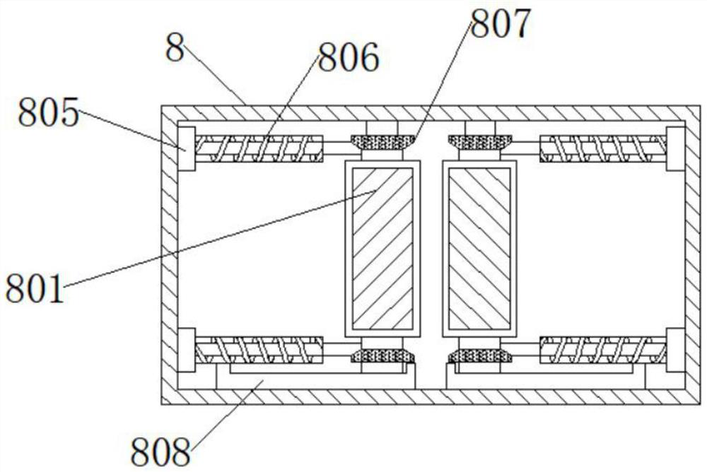
[0027] see Figure 1-7, the present invention provides a technical solution: a steel bar bending equipment for construction, including a bending device 1, the lower end of the bending device 1 is fixedly connected with a base 2, and the lower end of the base 2 is fixedly connected with a bracket 3, the The outer side of the bending device 1 is fixedly connected with an inspection door 4, the outer side of the inspection door 4 is fixedly connected with a sprin...


PUM


Abstract

The steel bar bending equipment for construction comprises a bending device, a base is fixedly connected to the lower end of the bending device, a support is fixedly connected to the lower end of the base, an access door is fixedly connected to the outer side of the bending device, a spring lock is fixedly connected to the outer side of the access door, and a pushing handle is fixedly connected to the right end of the bending device. And an editor is fixedly arranged at the upper end of the bending device, a conveying mechanism is fixedly connected to the upper end of the bending device, heat dissipation holes are fixedly connected to the upper end of the conveying mechanism, and a feeding port is fixedly formed in the right end of the conveying mechanism. By arranging the lifting rod, the universal wheels, the motor, the transmission machine and the wheels, when the bending device is moved, the motor is started to drive the transmission machine and then drive the wheels at the lower end, so that the universal wheels at the rear part are driven to move, the bending device can be pushed to a designated place, and workers can conveniently carry and push the bending device; and the workload of workers is reduced.

Description

technical field [0001] The invention relates to the technical field of building construction, in particular to a steel bar bending equipment for construction. Background technique [0002] Steel bar bending machine, one of the steel bar processing machines, the working mechanism is a horizontal working disc rotating on the vertical axis, the steel bar is placed at the dotted line position in the figure, the supporting pin is fixed on the machine tool, the center pin and the bending pin Installed on the working disk, the steel bar will be bent when the disk rotates. In order to bend steel bars of various diameters, there are several holes on the working disk for inserting and pressing the bending pin shaft, and the centers of different diameters can also be replaced accordingly. pin. [0003] However, the current existing steel bar bending device has a single design, requiring staff to manually put the steel bar into the steel bar bending device for bending. This method has ...

Claims


Application Information

Patent Timeline
Patent Type & Authority Applications(China)
IPC IPC(8): B21F1/00B21F23/00F16H57/04F16P1/02
Inventor 陈学斌高鹏
Owner 湖南凡工建筑工程有限公司
Why Eureka
Try Eureka