Connecting rod linkage type hatch cover turnover locking mechanism and turnover locking method thereof
A technology of flipping locking and locking mechanisms, which is applied to non-mechanical transmission-operated locks, building locks, motor vehicles, etc., and can solve problems such as unsatisfactory unlocking, opening and closing, unlocking and closing and locking, hatches that cannot be opened, etc. Achieve the effect of stable unlocking, opening and closing, locking and reliable connection
- Summary
- Abstract
- Description
- Claims
- Application Information
AI Technical Summary
Problems solved by technology
Method used
Image
Examples
specific Embodiment approach 1
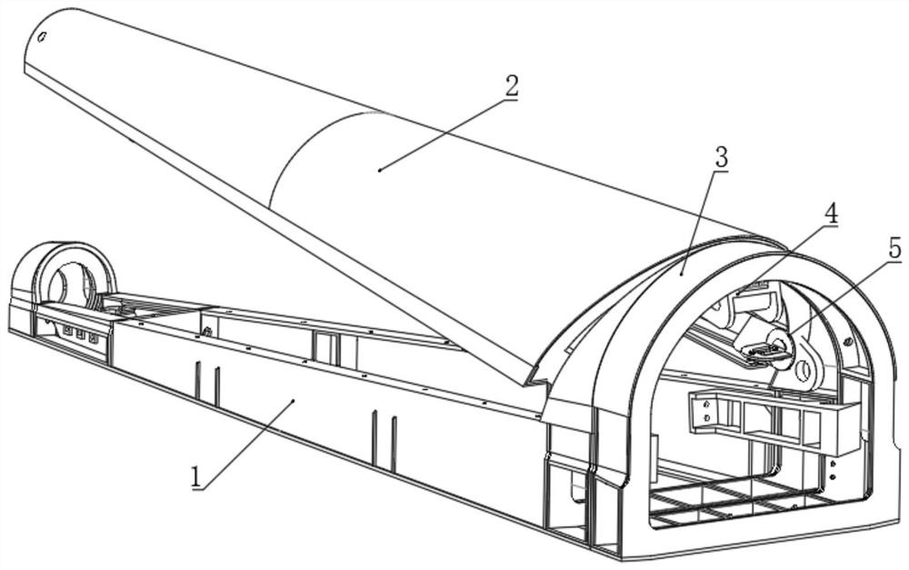
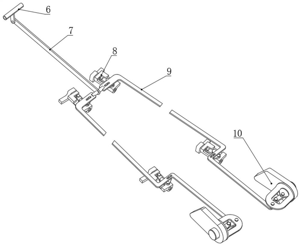
[0036] Specific implementation mode one: combine Figure 1 to Figure 10 Describe the present embodiment, a link linkage hatch cover flip locking mechanism of the present embodiment, which includes a flip mechanism 4 and a locking mechanism 5; the locking mechanism 5 includes a short connecting rod 6, a long connecting rod 7, two Pull rod 9, two axial locks 10 and four radial locks 8, two pull rods 9 are horizontally arranged on the left and right sides of the bottom end of the hatch cover 2 along the length direction of the hatch cover 2, and each pull rod 9 is formed by a U-shaped bar at the front end. It is connected with the rear end L-shaped bar from front to back in sequence. The front U-shaped bar openings of the two pull rods 9 are arranged opposite to each other. The four corners of the two front-end U-shaped bars are respectively processed with four radial locks. 8, the radial lock 8 in the locking mechanism 5 is used to realize the radial locking between the hatch co...
specific Embodiment approach 2
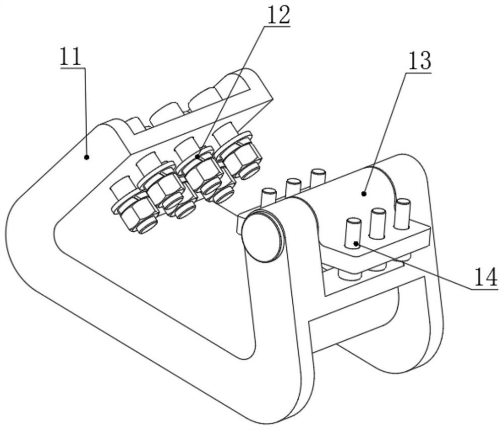
[0037] Specific implementation mode two: combination figure 1 To illustrate this embodiment, each radial lock 8 of this embodiment includes a shaft support 15, a shaft base 16, a radial crank 17, a radial slider 18 and a bolt shaft 19, and the shaft support 15 and the shaft base 16 are side by side opposite Setting, one end of the shaft support 15 is fixedly connected to the lower end surface of the top outer edge on the left and right sides of the cabin seat 1, the other end of the shaft support 15 is processed with a first radial pin hole, and one end of the shaft base 16 is fixedly connected to the hatch cover 2, The other end of the shaft base 16 is processed with a second radial pin hole, which is arranged coaxially with the first radial pin hole, and one end of the pin shaft 19 is inserted into the first radial pin hole of the shaft support 15. In the hole, the other end of the pin shaft 19 is inserted into the second radial pin hole of the shaft base 16, and the upper e...
specific Embodiment approach 3
[0038] Specific implementation mode three: combination Figure 1 to Figure 10 To illustrate this embodiment, each axial lock 10 in this embodiment includes an outer thick plate 28, an inner thick plate 20, an open support 21, a pin 1 22, a lock 23, an axial crank 24, a pin 2 25, Pin shaft 3 26 and axial slider 27, the outer thick plate 28 and the inner thick plate 20 are arranged side by side, one end of the outer thick plate 28 is fixedly connected with the inner wall of the cabin rear end 3, and the other end of the outer thick plate 28 is processed with a first shaft To the pin hole, one end of the inner thick plate 20 is fixedly connected to the root of the hatch cover 2, and the other end of the inner thick plate 20 is processed with a second axial pin hole, and the second axial pin hole is set coaxially with the first axial pin hole One end of the thick shaft of the lock catch 23 is sequentially inserted into the second axial pin hole of the inner thick plate 20 and the ...
PUM
 Abstract
Description
Claims
Application Information
 - Generate Ideas
- Intellectual Property
- Life Sciences
- Materials
- Tech Scout
- Unparalleled Data Quality
- Higher Quality Content
- 60% Fewer Hallucinations
Browse by: Latest US Patents, China's latest patents, Technical Efficacy Thesaurus, Application Domain, Technology Topic, Popular Technical Reports.
© 2025 PatSnap. All rights reserved.Legal|Privacy policy|Modern Slavery Act Transparency Statement|Sitemap|About US| Contact US: help@patsnap.com


