Angle steel forming device
A forming device and angle steel technology, applied in the direction of workpiece surface treatment equipment, metal rolling, metal rolling racks, etc., can solve the problems of small application range, inability to effectively clean impurities, etc., to ensure processing quality, simple structure, and expand The effect of scope
- Summary
- Abstract
- Description
- Claims
- Application Information
AI Technical Summary
Problems solved by technology
Method used
Image

Examples
Embodiment 1
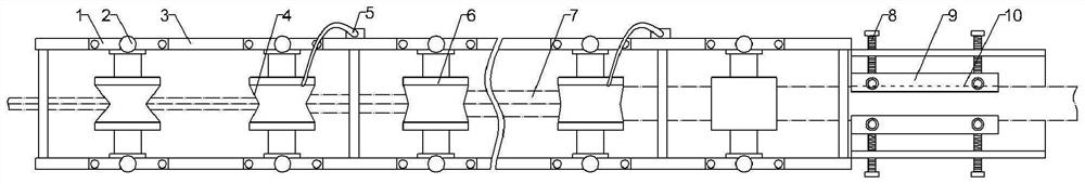
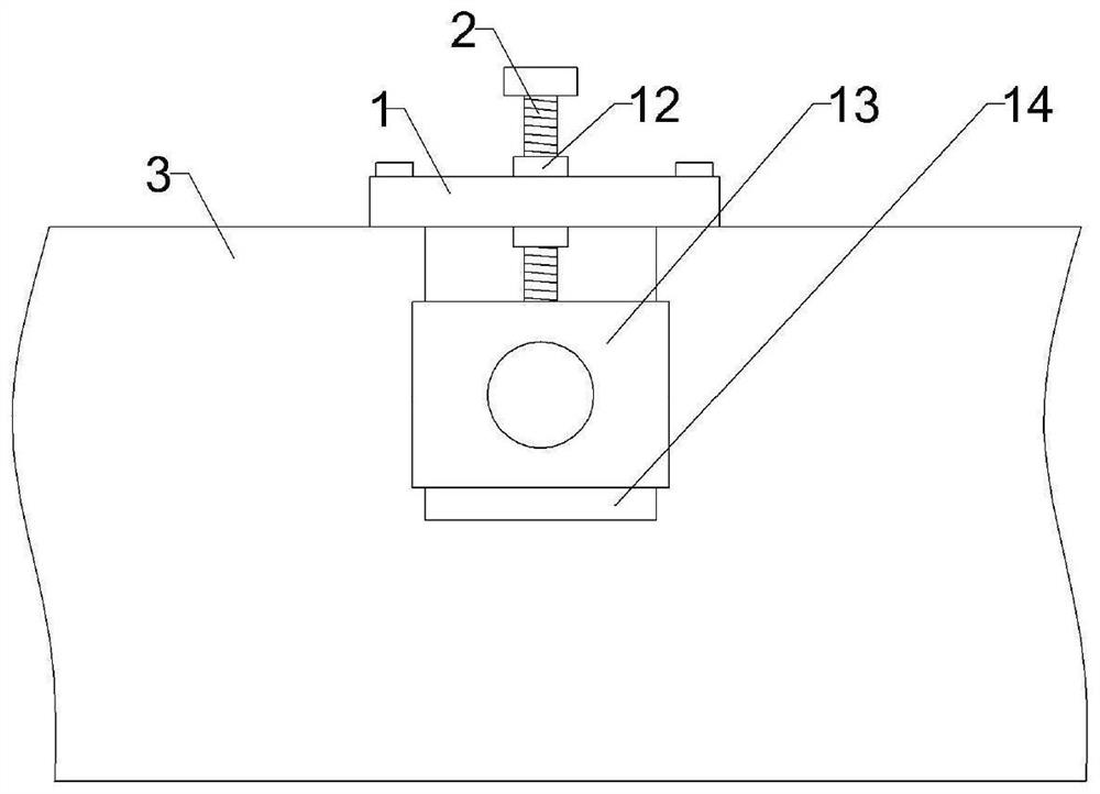
[0033] Such as figure 1 and figure 2 As shown, an angle steel forming device includes a forming tank 3, and multiple groups of pressure rollers are arranged in rows in the forming tank 3, figure 1 Part of the pressure rollers is shown in , each set of pressure rollers includes an upper pressure roller 6 and a lower pressure roller arranged up and down, a gap for the steel strip 7 to pass is formed between the upper pressure roller 6 and the lower pressure roller, and the lower pressure roller is connected There is a driving part, and the driving part adopts a motor (not shown in the figure). Forming groove 4 is integrally formed on the upper pressure roller 6, and a forming protrusion for cooperating with forming groove 4 is integrally formed on the lower pressure roller. The feed end (right end) to the discharge end (left end) increases one by one. Forming groove 3 side walls are symmetrically opened with multiple groups of mounting grooves 14, and mounting seats 13 are s...
Embodiment 2
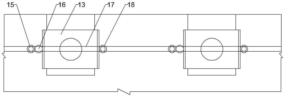
[0043] Such as image 3 As shown, the difference between this embodiment and Embodiment 1 is that the adjustment mechanism includes a driving gear (not shown in the figure), the driving gear is rotatably installed at one end of the forming groove 3, the driving gear is connected with a motor, and each mounting seat The first gear 18 is installed on the right side of 13, and the second gear 16 is installed on the left side of each mounting seat 13, and vertical racks are welded on both sides of the mounting seat 13, and the racks on both sides of the mounting seat 13 Engage with the first gear 18 and the second gear 16 respectively, the second gear 16 outer side (left side) is meshed with a transmission gear 15, the transmission gear 15 and the first gear 18 are coaxially connected with a sprocket, and the sprocket is tensioned There is a chain 17, and the driving gear drives the first gear 18 and the transmission gear 15 to rotate through the chain 17.
[0044] When adopting ...
Embodiment 3
[0046] Such as Figure 4 with Figure 5 As shown, the difference between this embodiment and the first or second embodiment is that a supporting mechanism for supporting the mounting seat 13 is provided in the mounting groove 14 . The support mechanism includes a first strut 20 and a second strut 19, the bottom ends of the first strut 20 and the second strut 19 are respectively hinged on both sides of the bottom of the installation groove 14, and the first strut 20 and the second strut 19 intersect Set and the first strut 20 is in the front, the bottom of the mounting seat 13 is provided with a dovetail groove (not shown in the figure), the tops of the first strut 20 and the second strut 19 are rotatably connected with balls, and the balls are rollingly connected to the dovetail. in the slot. The rear side of the first strut 20 and the front side of the second strut 19 are all provided with a strip-shaped connecting groove 21, and the first connecting ball is rollingly conne...
PUM
 Abstract
Description
Claims
Application Information
 - R&D
- Intellectual Property
- Life Sciences
- Materials
- Tech Scout
- Unparalleled Data Quality
- Higher Quality Content
- 60% Fewer Hallucinations
Browse by: Latest US Patents, China's latest patents, Technical Efficacy Thesaurus, Application Domain, Technology Topic, Popular Technical Reports.
© 2025 PatSnap. All rights reserved.Legal|Privacy policy|Modern Slavery Act Transparency Statement|Sitemap|About US| Contact US: help@patsnap.com