Electrospray ion source and ionization method based on electrospray technology

An electrospray ion source and ionization technology, which is applied in the field of ion sources, can solve the problems of low ion collection rate, low ionization efficiency, and low desolventization efficiency, and achieve improved ion transmission effect, good ion transmission effect, and easy desolvation. The effect of solvation

Pending Publication Date: 2022-03-29
HANGZHOU PUYU TECH DEV CO LTD
View PDF0 Cites 0 Cited by
  • Summary
  • Abstract
  • Description
  • Claims
  • Application Information

AI Technical Summary

Problems solved by technology

[0003] 1. At a high flow rate, it is easy to atomize insufficiently, and the desolventization efficiency is low, which makes the ionization efficiency low; because the high flow rate solution has a large flow rate, the atomizing gas atomizes the large flow solution into a relatively large volume of small droplets, and The high temperature desolvation gas is difficult to volatilize the concentrated solution droplets, resulting in low desolvation efficiency
[0004] 2. At a low flow rate, due to the relatively large capillary diameter, the solution with a small flow rate is easily discontinuous in the capillary, resulting in unstable spraying;
[0005] 3. The charged ions ejected from the capillary are dispersed in all directions. Only the ions close to the sampling cone can enter the mass spectrometer. The ions far away from the sampling cone rarely enter the sampling cone, and the ion collection rate is low.

Method used


Image

  • Electrospray ion source and ionization method based on electrospray technology
  • Electrospray ion source and ionization method based on electrospray technology

Examples


Embodiment 1

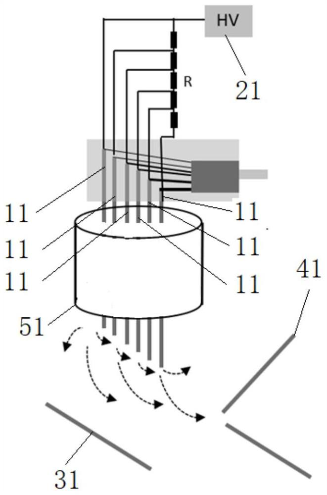
[0030] figure 1 A schematic structural view of the electrospray ion source of the embodiment of the present invention is given, as figure 1 As shown, the electrospray ion source includes:

[0031] A plurality of capillaries 11, the plurality of capillaries 11 arranged vertically are arranged in multiple rows, and from left to right, the height of the bottom end of each row of capillaries 11 gradually becomes lower;

[0032] A power supply 31 , the power supply 31 applies voltage to the capillary tubes 11 , the voltage of each column of capillary tubes 11 is the same, and the voltage of each column of capillary tubes 11 gradually decreases from left to right.

[0033] In order to improve the desolvation effect, further, the electrospray ion source also includes:

[0034] A gas conduit 51 surrounding the plurality of capillaries 11 .

[0035] In order to adapt to the liquids to be tested with different flow rates, furthermore, from left to right, the inner diameter of each ro...

Embodiment 2

[0049] An application example of the electrospray ion source and the ionization method based on electrospray technology according to Embodiment 1 of the present invention.

[0050] In this application example, if figure 1 As shown, a plurality of capillary tubes 11 are vertically arranged and arranged in multiple rows, and the height of the bottom end of each row of capillary tubes 11 is the same, and from left to right, the height of the bottom end of each row of capillary tubes 11 gradually becomes lower; each row of capillary tubes 11 The inner diameters of the capillaries are the same, and from left to right, the inner diameters of each row of capillary tubes 11 gradually become larger;

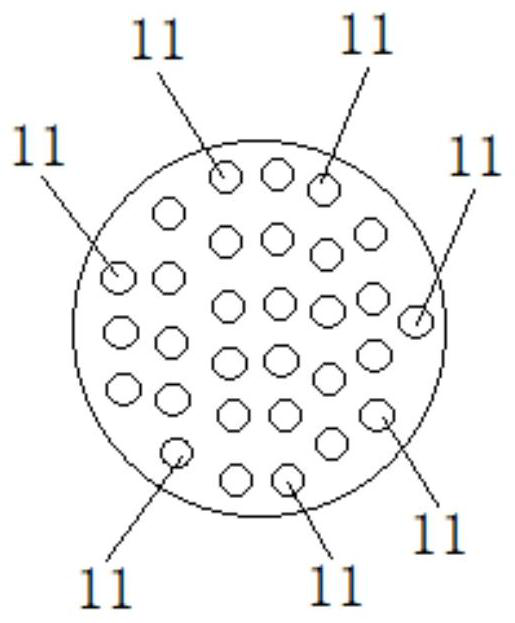
[0051] Such as figure 2 As shown, all capillary tubes 11 are in the same circle, and from left to right, the number of capillary tubes 11 in each column becomes larger and then smaller;

[0052] The power supply 21 applies a voltage to the capillary 11, the voltage of each column of ca...


PUM


Abstract

The invention provides an electrospray ion source and an ionization method, the electrospray ion source comprises a plurality of vertically arranged capillary tubes arranged in a plurality of columns, and the heights of the bottom ends of the capillary tubes in each column are gradually reduced from left to right; the power supply applies voltage to the capillary tubes, the voltage of each column of capillary tubes is the same, and the voltage of each column of capillary tubes is gradually reduced from left to right. The method has the advantages of wide application range and the like.

Description

technical field [0001] The invention relates to an ion source, in particular to an electrospray ion source and an ionization method based on electrospray technology. Background technique [0002] The existing ESI ion source uses a single capillary tube, which is connected to high voltage to charge the sample molecules, atomizing gas along the way to atomize the solution, and high temperature desolvating gas to evaporate the solvent. The deficiency that this technical scheme exists is: [0003] 1. At a high flow rate, it is easy to atomize insufficiently, and the desolventization efficiency is low, which makes the ionization efficiency low; because the high flow rate solution has a large flow rate, the volume of the atomizing gas atomizing the large flow solution into small droplets is relatively large, and The high-temperature desolvation gas is difficult to volatilize the concentrated solution droplets, resulting in low desolvation efficiency. [0004] 2. When the flow ra...

Claims


Application Information

Patent Timeline
Patent Type & Authority Applications(China)
IPC IPC(8): H01J49/16
CPCH01J49/167
Inventor 杨继伟尹伊君陆炫臻俞晓峰
Owner HANGZHOU PUYU TECH DEV CO LTD
Why Eureka
Try Eureka