
Cyanamide hydrolysis desolventizing system device

A system device and cyanamide technology are applied in the field of cyanamide hydrolysis and desolubilization system devices, which can solve the problems of slow production efficiency, low safety factor, large occupation space, etc., and achieve energy saving, increase output, and simple design. Effect

Inactive Publication Date: 2016-05-25
RUGAO ZHONGRU CHEM
View PDF7 Cites 0 Cited by
  • Summary
  • Abstract
  • Description
  • Claims
  • Application Information

AI Technical Summary

Problems solved by technology

[0002] In the past, in the production process of cyanamide, several groups of systems were required to work at the same time to achieve the production volume during desolventization. One group required two sets of air pumps. The previous production system had low safety factor, high energy consumption, and occupied a large space. In the past, a single The cooling of the cooling liquid in the cyanamide hydrolysis kettle is refrigerated by a special refrigerator, and then the cooling liquid is transported to the hydrolysis kettle, which consumes energy and costs a lot; at the same time, the carbon dioxide in the carbon dioxide liquid storage tank needs to be transported to the hydrolysis kettle in the past. It can only be transported to the hydrolysis tank from liquid to gaseous state. Usually, liquid carbon dioxide is naturally gasified at room temperature and then transported to the hydrolysis tank. However, this requires a lot of gasification time, resulting in slower production efficiency.

Method used


Image

  • Cyanamide hydrolysis desolventizing system device
  • Cyanamide hydrolysis desolventizing system device

Examples


Embodiment Construction

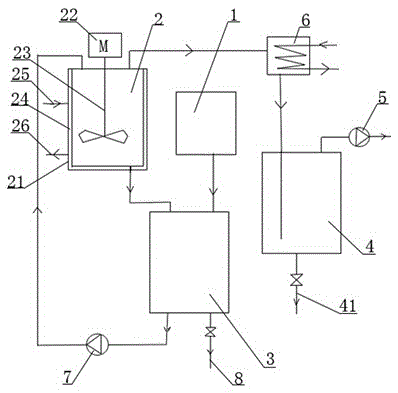
[0012] Refer to the attached figure 1 , a cyanamide hydrolysis and desolvation system device, which includes a hydrolysis mechanism 1, a thin film evaporator 2, a storage tank 3, a water removal tank 4, a vacuum pump 5, and a condenser 6, and the hydrolysis mechanism 1 is connected to the upper end of the storage tank 3 through a pipeline. , the outlet pipe of the lower end of the thin film evaporator 2 is connected to the upper end of the storage tank 3, the upper end of the thin film evaporator 2 is connected to the water removal tank 4 through the pipeline, the upper end of the water removal tank 4 is connected to the vacuum pump 5 through the pipeline, and the water removal tank 4 is connected to the thin film evaporator 2. A condenser 6 is installed on the inter-pipeline, the lower end of the storage tank 3 is connected to the upper end of the thin film evaporator 2 through a circulating pipeline, a delivery pump 7 is installed on the circulating pipeline, and a finished p...


PUM


Abstract

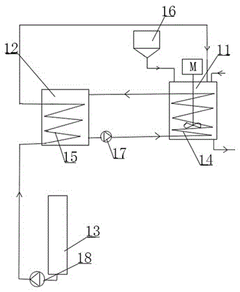
The invention relates to a cyanamide hydrolysis desolventizing system device including a hydrolysis mechanism, a thin film evaporator, a storage tank, a dewatering tank, a vacuum pump and a condenser; an outlet pipe at the lower end of the thin film evaporator is connected with the upper end of the storage tank; the upper end of the thin film evaporator is connected with the dewatering tank through a pipeline; the upper end of the dewatering tank is connected with the vacuum pump through a pipeline; the condenser is arranged on a pipeline between the dewatering tank and the thin film evaporator; the lower end of the storage tank is connected on the upper end of the thin film evaporator through a circulation pipeline; the circulation pipeline is provided with a conveying pump; the lower end of the storage tank is provided with a finished product outlet pipe. The cyanamide hydrolysis desolventizing system device has the advantages of simple design and convenient use, and each set of equipment has the yield probably four times that of conventional equipment; heat in a cooling water pond is brought away by using a theory that heat is absorbed during gasification of liquid carbon dioxide, so that a cooling liquid in the cooling water pond is cooled, energy consumption is saved, the carbon dioxide gasification is accelerated, the cost is reduced, and the hydrolysis kettle reaction efficiency is greatly accelerated; the storage tank and the thin film evaporator make a cyanamide intermediate product circularly desolventized through the conveying pump, and the desolventizing effect is prominent.

Description

technical field [0001] The invention relates to the field of cyanamide production systems, in particular to a cyanamide hydrolysis and desolvation system device. Background technique [0002] In the previous cyanamide production process, during desolvation, several groups of systems were required to work at the same time to achieve the production capacity. One group required two groups of air pumps. In the past, the production system had low safety factor, large energy consumption, and large space occupation. The cooling liquid of the cyanamide hydrolysis kettle is cooled by a special refrigerator, and then the cooling liquid is transported to the hydrolysis kettle, which consumes energy and costs a lot; at the same time, the carbon dioxide in the carbon dioxide liquid storage tank in the past needs to be transported to the hydrolysis kettle. It can only be transported into the hydrolysis kettle from liquid to gaseous state. Usually, liquid carbon dioxide is naturally gasifi...

Claims


Application Information

Patent Timeline
Patent Type & Authority Applications(China)
IPC IPC(8): B01J19/18B01J4/00C01C3/16B01D1/22B01D1/30
Inventor 蔡可建黄宏才常跃清
Owner RUGAO ZHONGRU CHEM
Learn More