
Cutter full life cycle management method and system and storage medium

A technology with a full life cycle and management method, applied in the field of CNC tool management, can solve the problems of cutting tools not reaching the level of intelligence, not reducing labor costs, and not timely replenishment, etc., to achieve unmanned and automated, and realize the full life cycle management and improve management efficiency

Pending Publication Date: 2022-03-29
深圳市坤同智能仓储科技有限公司
View PDF2 Cites 0 Cited by
  • Summary
  • Abstract
  • Description
  • Claims
  • Application Information

AI Technical Summary

Problems solved by technology

[0004] However, this kind of ordinary tool cabinet can only realize unmanned self-service pick-up of knives and records of employee pick-up information; it cannot meet the strict control requirements of the enterprise on the number of knives in and out of the warehouse under the self-service pick-up mode, and the number of employees can pick up; Only the lack of material information is displayed on the display screen of the machine. The warehouse management needs to actively inspect the machine and find that it can no longer take the initiative to give an early warning when the material is out of stock. situation; and under the premise that this kind of tool cabinet cannot realize self-service operation, the function of automatically replacing old knives with new knives in real time after returning waste knives still requires manual intervention to confirm the status of the knives and recycle them before manually setting permissions to achieve self-service Distribution, for some enterprises and factories that work at night, this management mode does not reduce labor costs, and the management of tools has not reached the maximum level of intelligence

Method used


Image

  • Cutter full life cycle management method and system and storage medium
  • Cutter full life cycle management method and system and storage medium

Examples


Embodiment Construction

[0052] In order to make it easier for those skilled in the art to understand the present invention, the specific implementation manners of the present invention will be described below with reference to the accompanying drawings. Preferred embodiments of the invention are shown in the accompanying drawings. However, the present invention can be implemented in many different forms and is not limited to the embodiments described in this specification. On the contrary, these embodiments are provided to make the understanding of the disclosure of the present invention more thorough and comprehensive.

[0053] It should be noted that when an element is referred to as being “fixed” to another element, it can be directly on the other element or there can also be an intervening element. When an element is referred to as being "connected to" another element, it can be directly connected to the other element or intervening elements may also be present. The terms "mounted", "fixed", "l...


PUM


Abstract

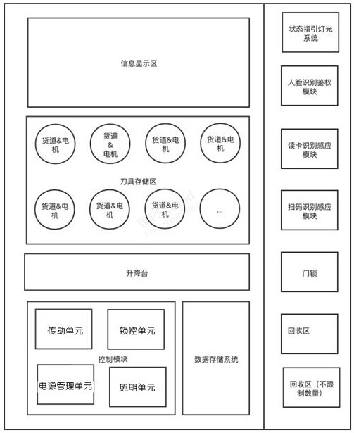
The invention discloses a tool full life cycle management system. The system comprises a background management system, a cloud server and a cabinet. The background management system is used for setting the authority of a user, analyzing and processing cutter management information and transmitting the processed information to corresponding equipment for execution; the cabinet comprises a cabinet body and an information display area, wherein a user operates and displays cutter information and user identity information in a cutter storage area; the cutter storage area is used for storing cutters needing to be managed and is fixed on the cabinet body; the lifting table working area is an area where the lifting table is used for bearing the tools received by the tool storage area; in the face recognition authentication area, a face recognition authentication module extracts face image features of the user and compares the face image features with corresponding face image information extracted and input by the background management system; the code scanning recognition sensing area is used for recognizing and sensing the cutter with the code; and the recovery area is an area for placing a return cutter.

Description

technical field [0001] The invention relates to the field of numerical control tool management, in particular to a tool life cycle management method, system and storage medium. Background technique [0002] At present, cutting tools are tools used for cutting in mechanical manufacturing, also known as cutting tools. With the vigorous development of modern manufacturing industry and the encouragement and support of national policies, driven by the strong demand of the manufacturing industry, while the Chinese tool market has achieved rapid development, the demand for tool management in the manufacturing industry is also increasing. In the machining industry, knives are used as raw materials for production, with a large amount and high value, and the knives work on CNC machine tools 24 hours a day. In order to ensure the smooth progress of production work in the factory warehouse, special personnel are often arranged to manage CNC knives on duty. [0003] In order to liberate...

Claims


Application Information

Patent Timeline
IPC IPC(8): G06Q10/06G06Q10/00G06Q50/04G07F7/06G07F7/10G07G1/00G06V40/16
CPCG06Q10/0631G06Q10/30G06Q50/04G07F7/06G07F7/10G07G1/0045Y02P90/30Y02W90/00
Inventor 赵佳芳何水林陈超
Owner 深圳市坤同智能仓储科技有限公司
Learn More