
Filament for ion source of ion implanter

An ion implanter, ion source technology, applied in the direction of discharge tubes, electrical components, circuits, etc., can solve the problems of filament size and shape design limitations, affecting the service life of the filament, and accelerating the consumption of the filament, so as to increase the available space, The effect of ensuring the hot electron release efficiency and reducing the filament current

Pending Publication Date: 2022-03-25
北京子牛亦东科技有限公司
View PDF0 Cites 0 Cited by
  • Summary
  • Abstract
  • Description
  • Claims
  • Application Information

AI Technical Summary

Problems solved by technology

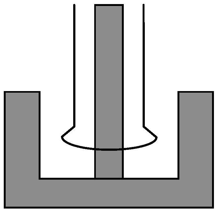
Due to the limited space inside the cathode cup and the fact that the filament cannot come into contact with the cathode cup and the intermediate rod, the size and shape of the filament is limited in design
In the prior art, in order to ensure the efficiency of the filament to release thermal electrons, the current of the filament is usually large, which accelerates the consumption of the filament itself, causing the filament to be prone to open circuit, which seriously affects the service life of the filament

Method used


Image

  • Filament for ion source of ion implanter
  • Filament for ion source of ion implanter
  • Filament for ion source of ion implanter

Examples


Embodiment Construction

[0026] Hereinafter, embodiments of the present disclosure will be described with reference to the drawings. It should be understood, however, that these descriptions are exemplary only, and are not intended to limit the scope of the present disclosure. Also, in the following description, descriptions of well-known structures and techniques are omitted to avoid unnecessarily obscuring the concept of the present disclosure.

[0027] Various structural schematic diagrams according to embodiments of the present disclosure are shown in the accompanying drawings. The figures are not drawn to scale, with certain details exaggerated and possibly omitted for clarity of presentation. The shapes of the various regions and layers shown in the figure, as well as their relative sizes and positional relationships are only exemplary, and may deviate due to manufacturing tolerances or technical limitations in practice, and those skilled in the art will Regions / layers with different shapes, s...


PUM

PropertyMeasurementUnit
diameteraaaaaaaaaa
diameteraaaaaaaaaa
lengthaaaaaaaaaa

Abstract

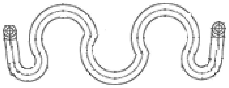
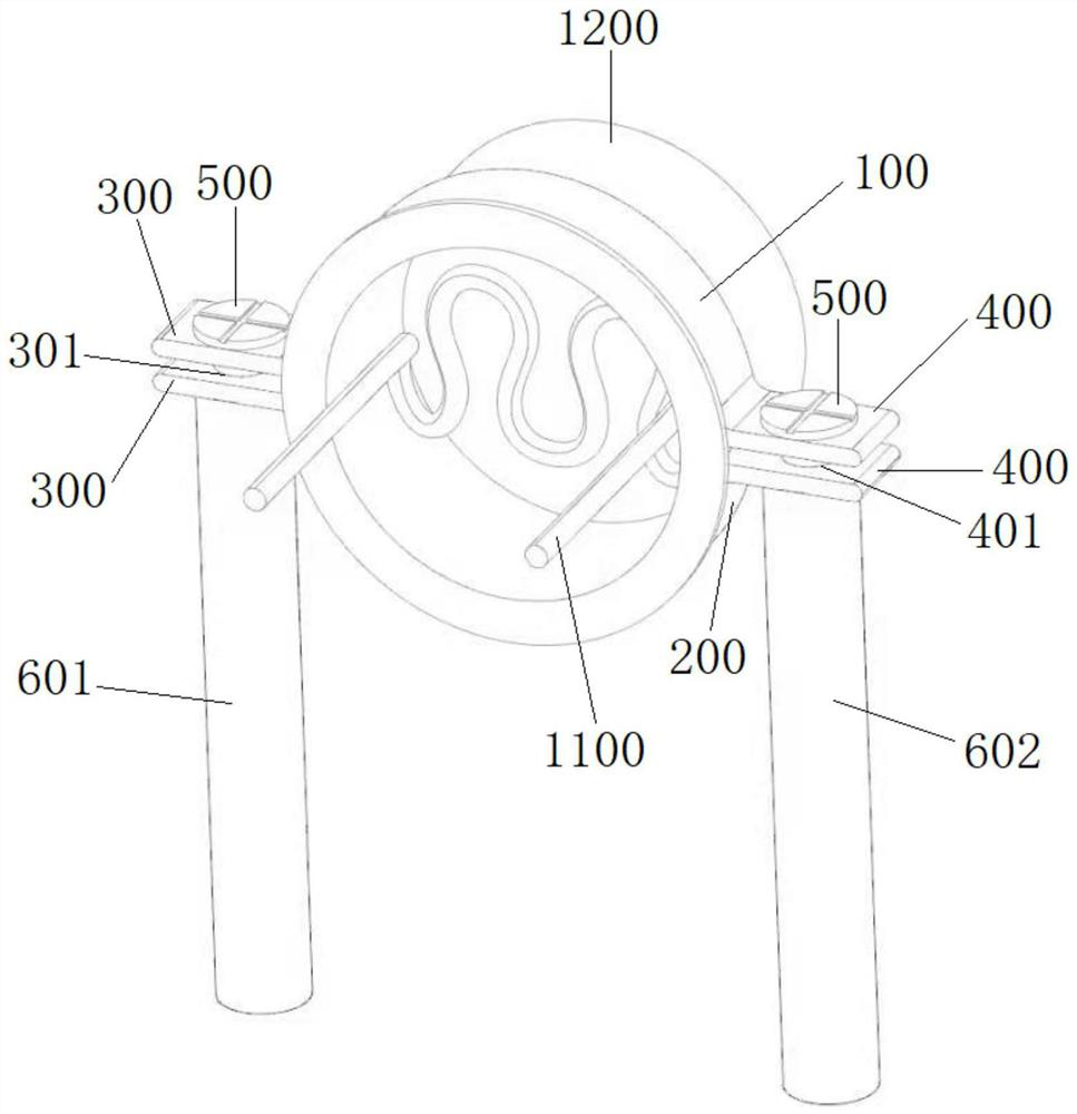
The invention relates to a filament for an ion source of an ion implanter. The longitudinal sectional area of an active part of the filament is 70-90mm < 2 >; the cathode fixing device used for the ion source comprises a fastening piece, a cathode fixing piece and an anode fixing piece, the clamp is arranged on the periphery of the cathode, a convex block is arranged on the clamp, a connecting hole is formed in the convex block, and the connecting hole is used for being matched with a fastener to fix the clamp on the cathode; and the supporting structure is connected with the convex block through a fastener. The lamp filament needs to be matched with a novel cathode fixing device for use, a middle rod in the center of the bottom of a cathode cup body is omitted through the cathode fixing device, and the available space in a cathode cavity is increased; on the basis, the longitudinal sectional area of the active part of the lamp filament is increased by changing the size and shape of the active part of the lamp filament, and the current of the lamp filament is reduced, so that the service life of the lamp filament can be prolonged while the hot electron release efficiency of the lamp filament is ensured.

Description

technical field [0001] The invention relates to the technical field of semiconductor manufacturing, in particular to a filament used for an ion source of an ion implanter. Background technique [0002] Ion implantation is a technique for selectively implanting impurity materials into semiconductor materials. After impurity materials are ionized in the ionization chamber, these ions are accelerated to form an ion beam with a set energy. The ion beam bombards the surface of the wafer and enters the wafer to reach a depth related to the energy. [0003] The ion implantation process is carried out in an ion implanter. An ion implanter generally includes an ion source, a mass spectrometer, an accelerator, and a processing chamber. The ion source includes a cathode and a filament. The thermal electrons generated by the filament located in the cathode cup bombard the ion source gas under the action of an electric field to ionize it into plasma. The number of thermal electrons re...

Claims


Application Information

Patent Timeline
Patent Type & Authority Applications(China)
IPC IPC(8): H01J37/08H01J37/317
CPCH01J37/08H01J37/3171
Inventor 陈涛李春龙刘小俊卓鸿俊
Owner 北京子牛亦东科技有限公司
Learn More