
High-frequency circuit, high-frequency device and communications apparatus

a high-frequency circuit and high-frequency technology, applied in electrical devices, digital transmission, semiconductor devices, etc., can solve problems such as deterioration of receiving sensitivity, failure to obtain sufficient improvement of receiving sensitivity, and likely breakage of switch circuits, etc., and achieve good receiving sensitivity and small current consumption

Active Publication Date: 2009-08-20
HITACHI METALS LTD
View PDF3 Cites 87 Cited by
  • Summary
  • Abstract
  • Description
  • Claims
  • Application Information

AI Technical Summary

Benefits of technology

[0020]Accordingly, an object of the present invention is to provide a high-frequency circuit usable in wireless communications selectively using at least two frequency bands, with good receiving sensitivity and small current consumption.

Problems solved by technology

However, the structure of the high-frequency circuit of WO 2006 / 003959 fails to obtain sufficient improvement in the receiving sensitivity.
Also, because a switch circuit, etc. are vulnerable to electrostatic surge, the switch circuit, etc. are likely broken in the circuit structure of WO 2006 / 003959, when electrostatic discharge (ESD) is applied to the antenna.
However, when the function of transmitting and receiving a wireless LAN is added to a mobile gear such as a cell phone, part of a transmitting signal for the mobile gear is likely to enter the wireless LAN system, saturating particularly a low-noise amplifier in a receiving path, and thus deteriorating the receiving sensitivity.
The circuit structure of JP 2003-273687 A coping with electrostatic discharge cannot fully solve such problem.
However, the high-frequency circuits of WO 2006 / 003959 and JP 2003-273687 A cannot fully handle IEEE 802.11n.

Method used


Image

  • High-frequency circuit, high-frequency device and communications apparatus
  • High-frequency circuit, high-frequency device and communications apparatus
  • High-frequency circuit, high-frequency device and communications apparatus

Examples


first embodiment

[1] First Embodiment

[0127](A) High-Frequency Circuit

[0128](1) Overall Structure

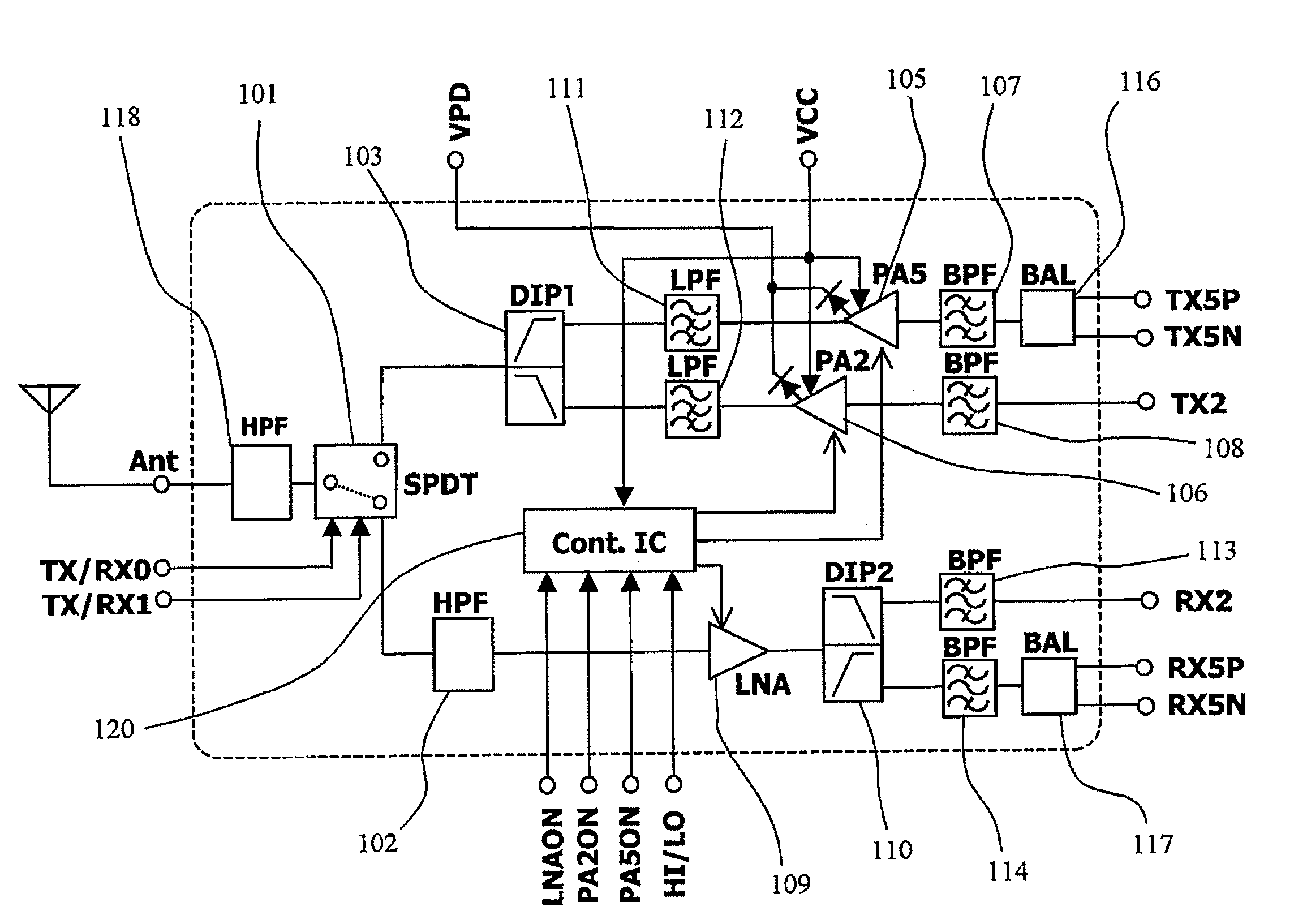
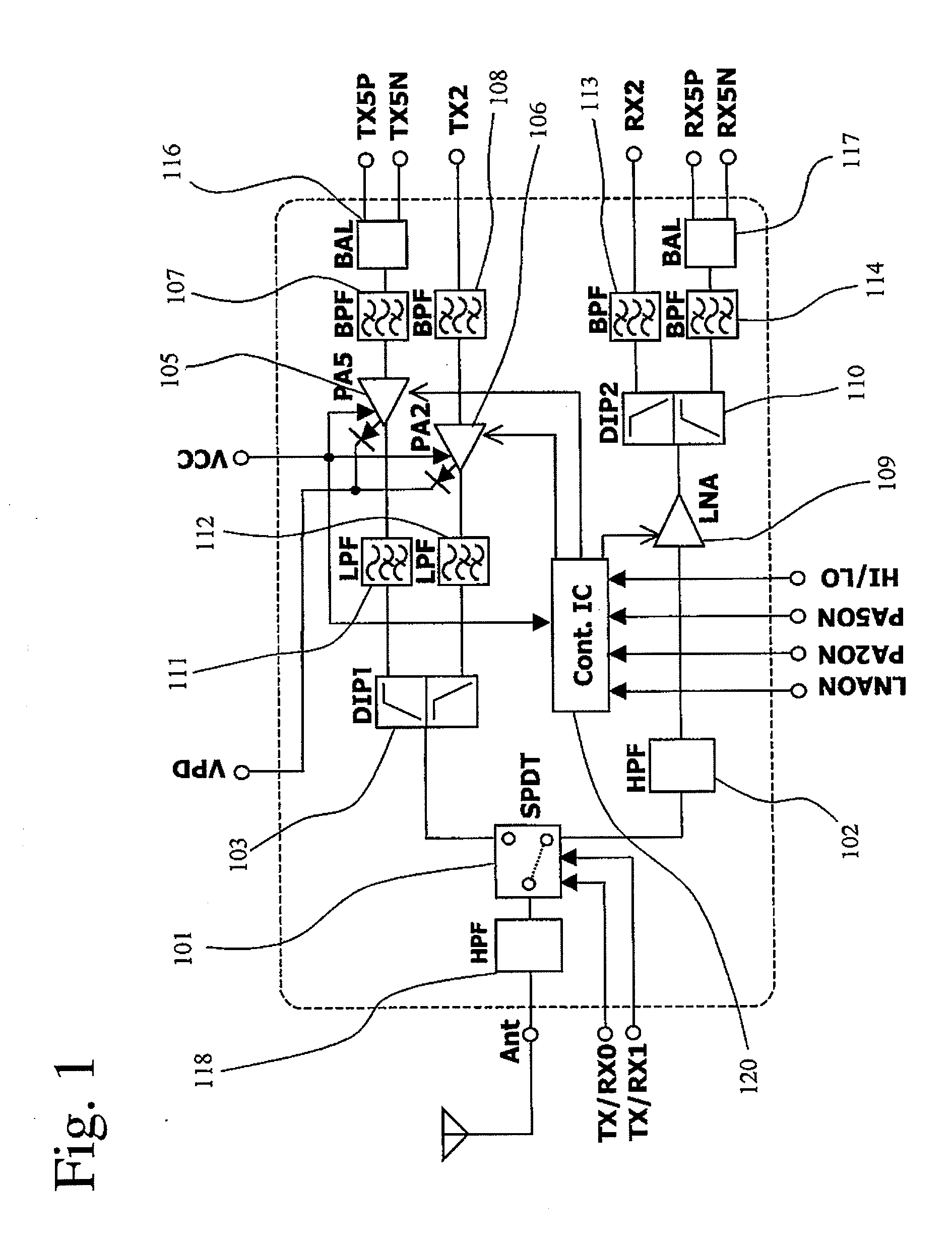
[0129]FIG. 1 shows a high-frequency circuit according to the first embodiment of the present invention commonly usable in two communications systems of a 2.4-GHz-band wireless LAN (IEEE 802.11b and / or IEEE 802.11g) and a 5-GHz-band wireless LAN (IEEE 802.11a). This high-frequency circuit comprises a switch circuit (SPDT) 101 connected to an antenna terminal Ant to be connected to a multiband antenna, a first diplexer circuit (DIP) 103 connected to the transmission path side of the switch circuit (SPDT) 101, and a highpass filter circuit (HPF) 118 as a first filter disposed between the antenna terminal Ant and the switch circuit 101. The first diplexer circuit 103 is constituted by a lower-frequency-side filter circuit passing a transmitting signal for a 2.4-GHz-band wireless LAN but attenuating a transmitting signal for a 5-GHz-band wireless LAN, and a higher-frequency-side filter circuit passing a transm...

second embodiment

[2] Second Embodiment

[0182](A) High-Frequency Circuit

[0183]FIG. 23 shows a high-frequency circuit according to the second embodiment of the present invention commonly usable in two communications systems of a 5-GHz-band wireless LAN (IEEE 802.11a) and a 2.4-GHz-band wireless LAN (IEEE 802.11b and / or IEEE 802.11g). This high-frequency circuit comprises a switch circuit (SPDT) 201 connected to an antenna terminal Ant to be connected to a multiband antenna, and a first diplexer circuit (DIP1) 202 connected to the transmission path side of the switch circuit (SPDT) 201. A highpass filter circuit (HPF) 218 is disposed as the first filter between the antenna terminal Ant and the switch circuit 201.

[0184]The first diplexer circuit 202 comprises a lower-frequency-side filter circuit passing a transmitting signal for a 2.4-GHz-band wireless LAN but attenuating a transmitting signal for a 5-GHz-band wireless LAN, and a higher-frequency-side filter circuit passing a transmitting signal for a 5...

third embodiment

[3] Third Embodiment

[0202](A) High-Frequency Circuit

[0203]FIG. 30 shows a high-frequency circuit according to a still further embodiment of the present invention commonly usable in two communications systems of a 5-GHz-band wireless LAN (IEEE802.11a) and a 2.4-GHz-band wireless LAN (IEEE802.11b and / or IEEE 802.11g). This high-frequency circuit comprises a highpass filter circuit (HPF) 318 as a first filter connected to an antenna terminal Ant to be connected to the multiband antenna, and a diplexer circuit (DIP) 301. The diplexer circuit301 comprises a higher-frequency-side filter circuit passing transmission and received signals for a 5-GHz-band wireless LAN but attenuating transmission and received signals for a 2.4-GHz-band wireless LAN, and a lower-frequency-side filter circuit passing transmission and received signals for a 2.4-GHz-band wireless LAN but attenuating transmission and received signals for a 5-GHz-band wireless LAN.

[0204]The higher-frequency-side filter circuit of ...


PUM


Abstract

A high-frequency circuit for wireless communications selectively using a first frequency band and a second frequency band lower than the first frequency band, comprising an antenna terminal; first and second transmission terminals to which transmitting signals in the first and second frequency bands are input; first and second receiving terminals from which received signals in the first and second frequency bands are output; a diplexer circuit for branching a first-frequency-band-signal path and a second-frequency-band-signal path; a switch circuit for switching a path for a transmitting signal and a path for a received signal; a low-noise amplifier circuit disposed between the switch circuit and the second receiving terminal for amplifying a received signal in the second frequency band; and first and second filter circuits disposed between the antenna terminal and the low-noise amplifier circuit in this order from the antenna terminal, both filter circuits passing a received signal in the second frequency band but blocking a frequency band lower than the second frequency band, and the band blocked by the first filter circuit being lower than the band blocked by the second filter circuit.

Description

FIELD OF THE INVENTION[0001]The present invention relates to a high-frequency circuit commonly usable in at least two communications systems, a high-frequency device having such high-frequency circuit, and a communications apparatus comprising it.BACKGROUND OF THE INVENTION[0002]Data communications by wireless LAN such as IEEE802.11 are now widely used, for instance, in personal computers (PCs), PC peripherals such as printers, hard disk drives and broadband routers, electronic apparatuses such as FAXs, refrigerators, standard televisions (SDTVs), high-definition televisions (HDTVs), digital cameras, digital video cameras and mobile phones, signal-transmitting means in automobiles and aircrafts, etc.[0003]As the wireless LAN standard, IEEE802.11a uses an orthogonal frequency division multiplexing (OFDM) modulation system in a frequency band of 5 GHz, supporting high-speed data communications of maximum 54 Mbps. IEEE802.11b uses a direct sequence spread spectrum (DSSS) system in an i...

Claims


Application Information

Patent Timeline
IPC IPC(8): H04L5/00H04B1/44
CPCH04B1/0057H04B1/44H01L2223/6677H01L2223/6688H01L2224/48227H01L2924/15313H01L2924/19105
Inventor FUKAMACHI, KEISUKEKEMMOCHI, SHIGERUHAGIWARA, KAZUHIRO
Owner HITACHI METALS LTD
Learn More