Visible light-medium wave infrared afocal optical system

An afocal optical system and visible light technology, applied in the field of optics, can solve the problems of difficult size control, difficult design, high processing cost, etc., and achieve the effect of compact structure, good fitability and easy assembly

Active Publication Date: 2022-03-25
CHANGCHUN INST OF OPTICS FINE MECHANICS & PHYSICS CHINESE ACAD OF SCI
View PDF4 Cites 0 Cited by
  • Summary
  • Abstract
  • Description
  • Claims
  • Application Information

AI Technical Summary

Problems solved by technology

The off-axis reflective afocal optical path can solve the problem of large aperture, multi-band, and common aperture, but it is difficult to process and assemble, and the processing cost is high. At the same time, the volume is large
[0004] For the design of large-aperture, multi-band, and common-aperture afocal optical systems, traditional transmissive optical systems are limited by materials, making the design difficult, complex and large in size
However, if the off-axis reflective optical path is used, there are problems of difficult processing and assembly and high processing cost, and the volume size is also difficult to control

Method used


Image

  • Visible light-medium wave infrared afocal optical system
  • Visible light-medium wave infrared afocal optical system
  • Visible light-medium wave infrared afocal optical system

Examples


Embodiment Construction

[0034] Hereinafter, embodiments of the present invention will be described with reference to the accompanying drawings. In the following description, the same blocks are denoted by the same reference numerals. With the same reference numerals, their names and functions are also the same. Therefore, its detailed description will not be repeated.

[0035] In order to make the object, technical solution and advantages of the present invention clearer, the present invention will be further described in detail below in conjunction with the accompanying drawings and specific embodiments. It should be understood that the specific embodiments described here are only used to explain the present invention, but not to limit the present invention.

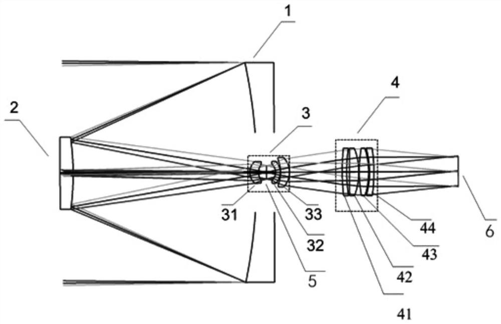
[0036] figure 1 The structure of the visible light-mid-wave infrared afocal optical system provided according to the embodiment of the present invention is shown.

[0037] Such as figure 1 As shown, the structure of the visible-medium-wav...


PUM

PropertyMeasurementUnit
viewing angleaaaaaaaaaa

Abstract

The invention provides a visible light-medium wave infrared afocal optical system. The visible light-medium wave infrared afocal optical system comprises a reflection type objective lens group and a transmission type eyepiece group, the reflective objective lens group comprises a first reflector and a second reflector; the transmission type eyepiece group comprises a field lens group and a collimating lens group; the first reflector is provided with a center hole. The second reflecting mirror is arranged in front of the first reflecting mirror and forms a Cassegrain structure with the first reflecting mirror; the field lens group is placed in the center of the first reflector, and the collimating lens group is placed behind the field lens group; the field lens group and the collimating lens group are composed of lenses. The light beam enters the field lens group after being reflected twice by the first reflector and the second reflector, and the field lens group is used for reducing the range of the light beam, so that the light beam with the reduced range enters the collimating lens group and is emitted in parallel after being refracted by the collimating lens group. According to the invention, large-aperture, multi-band and common-aperture imaging is realized, the structure is compact, and the adaptability is good; the method has the advantages of good imaging quality, high transfer function, small distortion and the like.

Description

technical field [0001] The invention relates to the field of optical technology, in particular to a visible light-medium wave infrared afocal optical system. Background technique [0002] An afocal optical system is an optical system in which both the incident and outgoing wavefronts are plane waves, and it has no converging and diverging effects on the beam, also known as a telescope system. In addition to being used for traditional telescopes and laser beam expanders, the afocal optical system can also be used as a part of the imaging optical system. Especially in the optical system that needs image motion compensation or image stabilization, the zoom effect of the afocal optical system on the beam is used, and a small-diameter flat mirror (ie, a fast mirror Fast Steering Mirror) is set between the afocal optical system and the imaging optical system. The relative motion between the target and the image during the exposure period of the detector is eliminated by fast mirr...

Claims


Application Information

Patent Timeline
Patent Type & Authority Applications(China)
IPC IPC(8): G02B17/08G02B27/30
CPCG02B17/0808G02B27/30
Inventor 张建萍张新史广维赵尚男
Owner CHANGCHUN INST OF OPTICS FINE MECHANICS & PHYSICS CHINESE ACAD OF SCI
Why Eureka
Try Eureka