
Bearing pad machining method

A processing method and pad technology, which are applied in the field of bearing pad processing and pad processing, can solve the problems of increased processing difficulty and difficulty in guaranteeing the dimensional accuracy of the pad, and achieve the effects of easy realization, high processing efficiency and simple process flow.

Pending Publication Date: 2022-03-25
HARBIN TURBINE +1
View PDF9 Cites 1 Cited by
  • Summary
  • Abstract
  • Description
  • Claims
  • Application Information

AI Technical Summary

Problems solved by technology

[0003] The purpose of the present invention is to solve the problems in the prior art that within the range of 150 mm length of the bearing pad, the wall thickness of the pad meets the tolerance requirement of 0.01 mm, which increases the processing difficulty and the dimensional accuracy of the pad is difficult to guarantee, and further provides a Processing method of bearing pad

Method used


Image

  • Bearing pad machining method
  • Bearing pad machining method
  • Bearing pad machining method

Examples


specific Embodiment approach 1

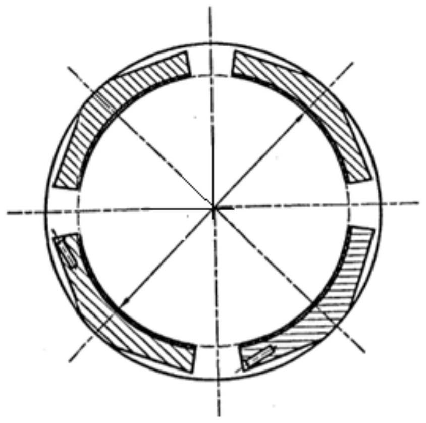
[0023] Specific implementation mode one: combine Figure 1-Figure 3 Describe this embodiment, the described method for processing a bearing pad, the method is realized according to the following steps:

[0024] Step 1: Prepare the blank, the outer surface of the blank is a circular forging;

[0025] Step 2: Turning: turn the inner hole of the forging, and roughly machine the outer circle and end face of the forging;

[0026] Step 3: Pouring the bearing alloy at the inner hole of the forging;

[0027] Step 4: Semi-finishing machining: semi-finishing the inner hole, outer circle and end face, leaving a machining allowance on each side;

[0028] Step 5: Aging treatment: place the workpiece after semi-finishing in step 4 in an environment of 15-30 degrees Celsius for 72 hours;

[0029] Step 6: Finish turning the end face, semi-finishing the inner hole and outer circle: based on the inner hole, process the outer circle surface, leave milling allowance, and finish turning the end...

specific Embodiment approach 2

[0036] Specific implementation mode two: combination Figure 1-Figure 2 Describe this embodiment, a bearing pad processing method described in this embodiment, the inner hole of the forging is processed by semi-finishing in step 4, the radius of the inner hole is left with a machining allowance of 2 mm, and the radius of the outer circle is left with a machining allowance 1mm, each end face processing allowance is 0.5mm. Other compositions and connection methods are the same as those in Embodiment 1.

specific Embodiment approach 3

[0037] Specific implementation mode three: combination Figure 1-Figure 2 This embodiment is described, a bearing pad processing method described in this embodiment, in step 6, a machining allowance of 0.5 mm is left for the radius of the outer circle of the forging, and a machining allowance of 1.5 mm is left for the radius of the inner hole. Other compositions and connection methods are the same as those in Embodiment 1.


PUM


Abstract

The invention relates to a bearing pad machining method, in particular to a bearing pad machining method, and aims to solve the problems that in the prior art, within the 150 mm length range of a bearing pad, the machining difficulty is increased due to the fact that the wall thickness size of the pad meets the tolerance requirement of 0.01 mm, and the size precision of the pad is difficult to guarantee. The technical problem is solved through the following scheme that firstly, a blank is prepared; 2, turning machining is carried out; thirdly, bearing alloy is poured; fourthly, semi-finish turning is conducted; step 5, aging treatment; sixthly, the end face is subjected to finish turning; step 7, scribing; eighthly, linear cutting machining is conducted; 9, turning an inner hole; tenthly, the inclined face and the radiating face of the arc-shaped body are machined through linear cutting equipment according to the contour line in the seventh step; 11, processing a back arc and a positioning hole; and twelfthly, coping treatment is conducted. The machining method belongs to the field of machining.

Description

technical field [0001] The invention relates to a pad processing method, in particular to a bearing pad processing method, which belongs to the field of mechanical processing. Background technique [0002] Four bearing pads of a steam turbine unit are installed in the bearing shell, and each bearing pad is suspended on the oil deflector rings on both sides through two cylindrical pins. Since the back arc of the pad and the inner hole are eccentric, the back arc of the pad It is in line contact with the housing, and the tiles can swing freely in the housing. The single piece size of the inner hole of the tile is After assembly, only the size of the inner hole in the middle of the two tiles in the 45° direction is According to the design principle, the assembly size tolerance is only 0.02mm, and the wall thickness accuracy of a single piece of tile needs to be controlled within 0.01mm. Because the back arc and the inner hole are eccentric structures, it is necessary to en...

Claims


Application Information

Patent Timeline
Patent Type & Authority Applications(China)
IPC IPC(8): B23P15/00
CPCB23P15/00
Inventor 吕思佳林彬彬张隆张武成杨庆仁崔会彬吴雯莉孙庆山
Owner HARBIN TURBINE
Learn More