High-frequency-response wide-range MEMS friction resistance sensor

A sensor with a large range of technology, applied in the field of MEMS sensors, can solve the problems of inability to accurately measure the friction distribution of the aircraft surface, fail to meet the measurement requirements, and low sensitivity of micro balances, achieve high frequency response, improve measurement sensitivity, and reliability high effect

Active Publication Date: 2022-03-22
中国空气动力研究与发展中心超高速空气动力研究所
View PDF12 Cites 1 Cited by
  • Summary
  • Abstract
  • Description
  • Claims
  • Application Information

AI Technical Summary

Problems solved by technology

In 2010, Joseph A. Schetz et al [Direct measurement of skin friction in complex flows, 48th AIAAAerospace Sciences Meeting Including the New Horizons Forum and AerospaceExposition 4-7 January 2010, Orlando, Florida [C].] developed a strain type Micro-friction balance, the friction measurement test of the model surface is carried out in the flow field of the hypersonic wind tunnel with Ma=4, but this kind of micro-balance has low sensitivity, poor temperature stability, and large volume, so it cannot be used to accurately measure the surface of the aircraft The distribution of friction
With the rapid development of hypersonic technology, there is an urgent demand for friction measurement in a pulsed shock wave wind tunnel test environment with a running time of milliseconds and a measurement range of 1Pa-1000Pa. The aforementioned MEMS friction sensor (a micromechanical friction sensor) Resistance sensor and production method, patent number 201418003582.X, 2017.07.) cannot meet the measurement requirements

Method used


Image

  • High-frequency-response wide-range MEMS friction resistance sensor
  • High-frequency-response wide-range MEMS friction resistance sensor
  • High-frequency-response wide-range MEMS friction resistance sensor

Examples


Embodiment 1

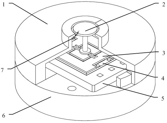
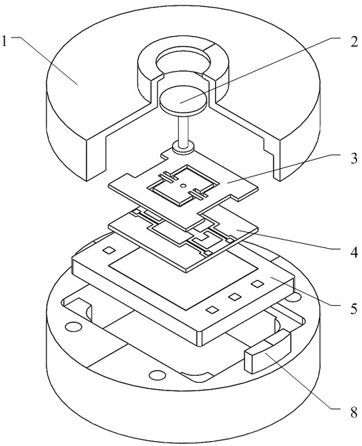
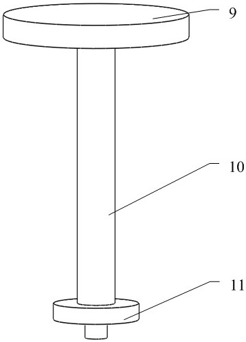
[0051] like figure 1 , figure 2 As shown, the high-response and large-range MEMS friction sensor of this embodiment includes a package cover 1 , a floating element 2 , a silicon microstructure 3 , an electrode substrate 4 , an interface circuit 5 and a package socket 6 . Wherein, the floating element 2 comprises a floating unit 9, a pole 10 and a positioning step 11, such as image 3 As shown; the silicon microstructure 3 includes a support frame 12, an elastic beam 13 and a vibrating plate 14, such as Figure 4 Shown; Electrode substrate 4 comprises lead electrode 15, metal electrode 16 and glass boss 17, as Figure 5 As shown; the vibrating plate 14 of the silicon microstructure 3 and the metal electrode 16 of the electrode substrate 4 form a differential sensitive capacitor 18 to realize differential capacitance detection, as Image 6 As shown; the floating element 2, the silicon microstructure 3 and the electrode substrate 4 together constitute the head structure of t...


PUM


Abstract

The invention belongs to the field of MEMS (Micro Electro Mechanical System) sensors in a micro electro mechanical system, and discloses a high-frequency-response wide-range MEMS friction resistance sensor. The MEMS friction resistance sensor is composed of a packaging cover plate, a meter head structure, an interface circuit and a packaging tube socket. The packaging cover plate and the packaging tube seat are cylinders which are stacked up and down, and the meter head structure and the interface circuit are mounted in central cavities of the packaging cover plate and the packaging tube seat; the header structure is a main component of the MEMS friction sensor, is composed of a floating element, a silicon microstructure and an electrode substrate, and is used for sensing the friction on the surface of an aircraft model and converting the friction into a differential capacitance signal. According to the MEMS friction resistance sensor, a three-dimensional MEMS meter head structure in which a floating element is flush with a wall surface to be measured and a signal output microstructure is isolated from a wind tunnel flow field is adopted, and a plate capacitance differential detection and measurement method is adopted.

Description

technical field [0001] The invention belongs to the field of MEMS sensors in micro-electromechanical systems, and in particular relates to a MEMS friction sensor with high frequency response and large range. Background technique [0002] The MEMS friction sensor is mainly used to test the friction on the surface of the aircraft, and then determine the size and distribution of the friction on the surface of the aircraft, which is of great significance to the design of the aircraft. The traditional surface friction measurement device is mainly a micro strain friction balance, but it is difficult to be widely used in the field of aircraft design due to the limitation of sensitivity, temperature, volume and cost. The MEMS friction sensor based on micro-electromechanical system technology has outstanding advantages such as small size, low cost, and high reliability, and can be widely used in aircraft design and other fields. [0003] At present, there are many literatures introd...

Claims


Application Information

Patent Timeline
Patent Type & Authority Applications(China)
IPC IPC(8): G01M9/06G01N19/02
CPCG01M9/06G01N19/02
Inventor 王雄郭辉辉朱涛郭治江王南天许晓斌崔炜栋
Owner 中国空气动力研究与发展中心超高速空气动力研究所
Why Eureka
Try Eureka