


Quick Research
Generate reliable direction feasibility study reports for your R&D in just a few steps.

Technical Q&A
Discover and master advanced knowledge NOW. Basics, ideas, possibilities, all at once.

Find Solutions
As an expert in R&D theories, this can generate solutions to your technical problems instantly.

Evaluate Feasibility
Analyze your overall solution with one click, know your potential R&D risks in advance.

Monitor Landscape
Get weekly tech updates, stay abreast of the latest tech innovations and key insights.
Integrated brake-by-wire system and control method of redundant control coil
A brake-by-wire, integrated technology, applied in brake safety systems, brake control systems, brakes, etc., can solve problems such as casualties, failures, and inability to control the switch state of solenoid valves, reducing failure rates and preventing wheel locks. dead effect
- Summary
- Abstract
- Description
- Claims
- Application Information
AI Technical Summary
Problems solved by technology
Method used
Image

Examples
Embodiment
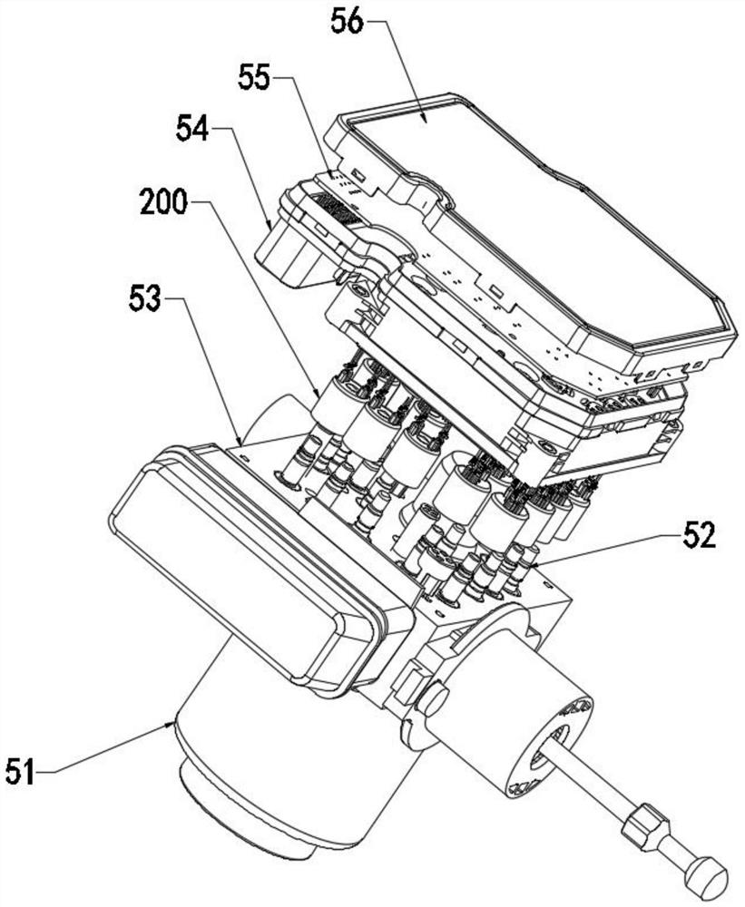
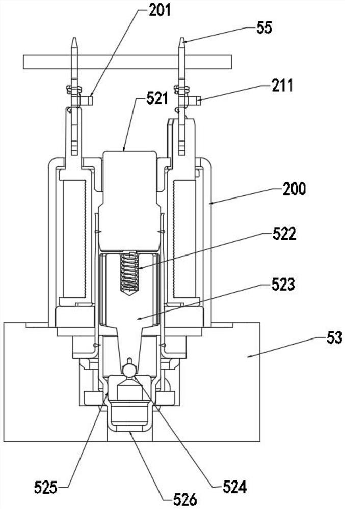
[0057] see Figure 1-8 , the present invention provides a technical solution: an integrated brake-by-wire system. The architecture of the integrated brake-by-wire system includes a main power supply, a main control loop, a backup power supply, a backup control loop, a master cylinder isolation valve, and a pressure chamber isolation valve. , booster valve, pressure reducing valve. The solid line in the figure represents the current circuit, and the dotted line represents the hydraulic circuit.
[0058] The main control loop receives the instructions determined by the automatic driving control system according to the specific situation, and applies current or voltage to the coils of the solenoid valves in the system according to the requirements, through the isolation valve of the master cylinder, the isolation valve of the pressure chamber, the booster valve and the pressure relief valve. Coordinated action realizes wheel braking and anti-lock braking functions during driving...
Embodiment 2
[0065] Embodiment 2 is a case of an open circuit failure of the main cylinder isolation valve coil. When the main coil winding of the master cylinder isolation valve is disconnected, the master cylinder isolation valve as a normally open valve cannot be closed by the main control circuit during the active pressurization process, causing the brake fluid to flow back to the master cylinder. invalidated. At this time, the backup control loop will apply positive voltage or current to the backup coil winding according to the judgment made by the autopilot system to take over the control of the isolation valve of the master cylinder, and control the isolation valve of the master cylinder to close to maintain the wheel cylinder pressure formed by the active pressure build-up , thereby restoring the braking ability.
[0066] In the above scenario, the processing logic of the backup control loop for the coil failure is applicable to any solenoid valve that needs to cooperate in the pr...
PUM
 Abstract
Description
Claims
Application Information
 - R&D Engineer
- R&D Manager
- IP Professional
- Industry Leading Data Capabilities
- Powerful AI technology
- Patent DNA Extraction
Browse by: Latest US Patents, China's latest patents, Technical Efficacy Thesaurus, Application Domain, Technology Topic, Popular Technical Reports.
© 2024 PatSnap. All rights reserved.Legal|Privacy policy|Modern Slavery Act Transparency Statement|Sitemap|About US| Contact US: help@patsnap.com