Preparation method of invisible wing surface component

A stealth wing and component technology is applied in the field of stealth wing surface component preparation based on rapid detection of material reflectivity, and can solve problems such as inability to effectively monitor overall reflectivity performance.

Active Publication Date: 2022-03-18
BEIJING RES INST OF MECHANICAL & ELECTRICAL TECH
View PDF10 Cites 0 Cited by
  • Summary
  • Abstract
  • Description
  • Claims
  • Application Information

AI Technical Summary

Problems solved by technology

This method only mentions the detection of the reflectivity of the absorbing functional layer material, but it cannot effectively monitor the overall reflectance performance of the absorbing functional layer material and the dielectric material. According to the conventional method, the broadband reflectivity of the absorbing material can only be Can only be detected after fully cured and prepared as a sample

Method used


Image

  • Preparation method of invisible wing surface component
  • Preparation method of invisible wing surface component
  • Preparation method of invisible wing surface component

Examples


Embodiment 1

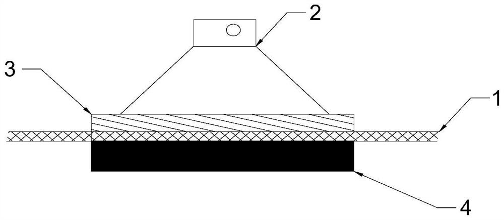
[0048] Example 1: The preparation method of the empennage airfoil using the structure of "glass fiber reinforced plastic + co-cured wave-absorbing patch + shielding bottom layer"

[0049] In this structure, it is necessary to test the electrical properties of the FRP material and the co-cured wave-absorbing patch material before forming. The specific preparation method is as follows:

[0050] Step 1: Determine the layered thickness of the wave-absorbing fin structure

[0051] Glass fiber cloth is used as the medium layer material, the co-cured wave-absorbing patch is used as the wave-absorbing functional layer material, and the single-layer carbon fiber cloth is used as the shielding layer, which is laid on the internal dimension surface of the empennage, and epoxy resin is applied between the layers. According to the autoclave Molding process, complete the preparation and molding of the wave-absorbing fin, conduct anatomical measurement on it, obtain the structural thickness ...

Embodiment 2 Embodiment 1

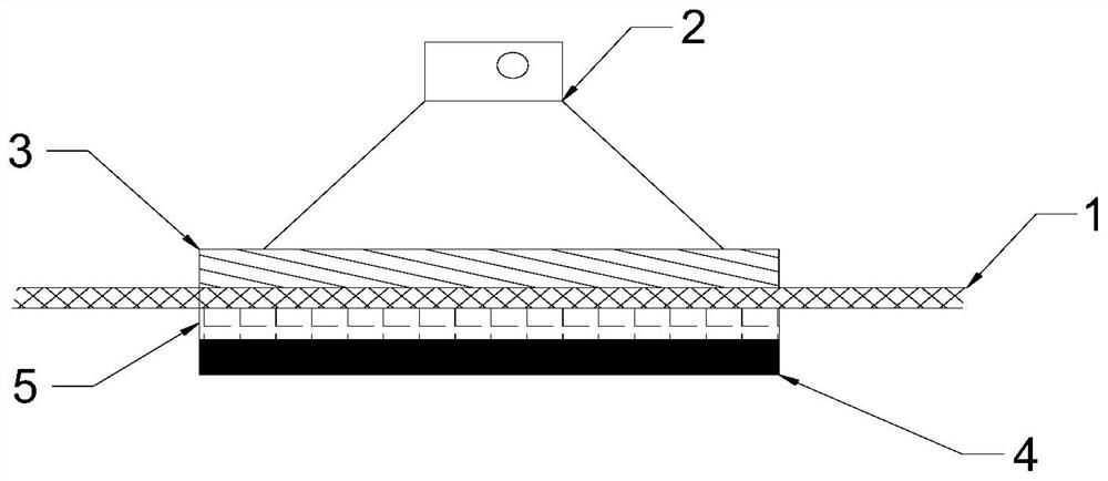
[0061] Example 2 Example 1: Preparation method of empennage airfoil using "quartz fiber reinforced composite material + wave-absorbing cloth + shielding bottom layer" structure

[0062] In this structure, the absorbing cloth material is the focus of detection, and it is necessary to consider the process error. It is required that the absorbing cloth material and the quartz fiber-reinforced composite material within a reasonable thickness deviation range can cooperate to achieve broadband absorbing characteristics:

[0063] Step 1: Determining the layered thickness of the leading edge structure of the stealth wing

[0064] Quartz fiber cloth is used as the material of the medium layer, and wave-absorbing cloth is used as the material of the wave-absorbing functional layer. Polyurethane resin is applied between the layers. According to the molding process, the leading edge of the stealth wing is prepared and molded. Anatomical measurements are made to obtain the structural thickn...

Embodiment 3

[0071] Embodiment 3: the preparation method of the empennage airfoil surface adopting "quartz fiber reinforced composite material+absorbing cloth 1+absorbing cloth 2+shielding bottom layer" structure

[0072] In this structure, the two-layer wave-absorbing cloth material is the focus of detection. It is necessary to consider the process error. It is required that the wave-absorbing cloth material and the quartz fiber-reinforced composite material within a reasonable thickness deviation range can cooperate to achieve broadband wave-absorbing characteristics. According to the preparation needs, The electrical performance testing shall be carried out separately for the two absorbing layers.

[0073] Step 1: Determine the thickness of the leading edge structure of the stealth wing

[0074] Quartz fiber cloth is used as the medium layer material, uncured wave-absorbing cloth with conductive coating shielding bottom layer is used as the wave-absorbing functional layer material, and ...


PUM

PropertyMeasurementUnit
Lengthaaaaaaaaaa
Widthaaaaaaaaaa
Thicknessaaaaaaaaaa

Abstract

The invention discloses a preparation method of a stealth airfoil component, the stealth airfoil component is composed of a dielectric layer material, a wave-absorbing functional material and a shielding bottom layer material, and the wave-absorbing functional material is rapidly detected before the stealth airfoil component is manufactured and formed. A device used for testing comprises a reflectivity field measuring instrument, a standard reference medium layer plate and a shielding bottom plate, and the testing is carried out according to the following steps that a wave-absorbing functional material, the standard reference medium plate and the shielding bottom plate form a multi-layer structure, and the layering sequence of the multi-layer structure is required to be consistent with the actual layering sequence of an invisible wing surface component; the standard reference dielectric plate is made of a dielectric layer material, and the thickness of the standard reference dielectric plate is consistent with the designed thickness of the dielectric layer material in an actual laying layer. A reflectivity field measuring instrument is pressed on the outer surface of the multi-layer composite structure for reflectivity testing, and whether the stealth performance of the wave-absorbing functional material used for forming the stealth wing surface part reaches an expected index or not is judged according to whether the test result R reaches the standard or not.

Description

technical field [0001] The invention belongs to the technical field of radar stealth airfoil components, and relates to a method for preparing stealth airfoil components based on rapid detection of material reflectivity. This technical scheme can be applied to the radar stealth design of various stealth aircrafts such as aircraft / missile wings, empennage, and rudder surface, and is also suitable for the design of stealth structural components with complex shapes such as air inlets and tail nozzles. Background technique [0002] The wing surface is one of the main radar scattering sources of the aircraft. In order to reduce the radar echo of the aircraft and improve the stealth performance of the aircraft, it is necessary to use multi-layer wave-absorbing composite materials with broadband wave-absorbing characteristics. [0003] Chinese invention patents "A Honeycomb Sandwich Graphene Stealth Front and Its Processing Method" (Application No.: CN202011162303.5), "A Stealth / Be...

Claims


Application Information

Patent Timeline
IPC IPC(8): B32B17/02B32B17/10B32B27/38B32B9/00B32B9/04B32B27/06B32B27/40B32B33/00B32B37/06B32B37/10B64F5/10
CPCB32B5/02B32B27/12B32B27/38B32B27/06B32B27/40B32B33/00B32B37/06B32B37/10B64F5/10B32B2262/101B32B2262/10B32B2262/106B32B2307/212
Inventor 郝璐郭晓铛张松靖唐建国
Owner BEIJING RES INST OF MECHANICAL & ELECTRICAL TECH
Why Eureka
Try Eureka