End ring turning process

A turning and end ring technology, applied in the field of generator rotor end ring processing, can solve the problems of influence, traditional technology can not meet technical requirements, endanger normal operation, etc. effect of brightness

Pending Publication Date: 2022-03-18
YANTAI WANLONG VACUUM METALLURGY
View PDF10 Cites 0 Cited by
  • Summary
  • Abstract
  • Description
  • Claims
  • Application Information

AI Technical Summary

Problems solved by technology

The groove of the end ring is mainly the guide bar soldered to the outer circle of the motor core. It connects the two ends of all the guide bars and plays the role of conducting current. If there is a problem, it will affect the power generation of the whole machine and endanger the normal run
With the development of current technology and equipment, the requirements for machining accuracy, smoothness, and surface brightness of the end ring are getting higher and higher. Can not meet the current technical requirements, need to improve the traditional process

Method used


Image

  • End ring turning process
  • End ring turning process
  • End ring turning process

Examples


Embodiment 1

[0035] A copper end ring turning process, comprising the following process steps:

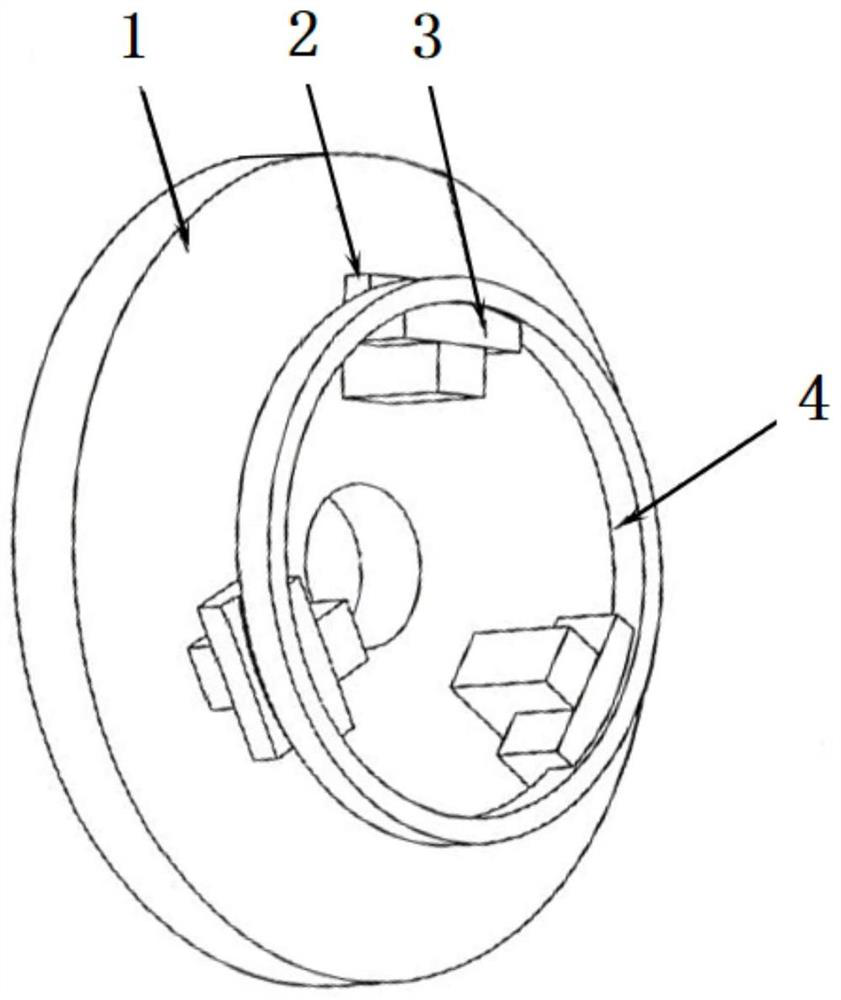
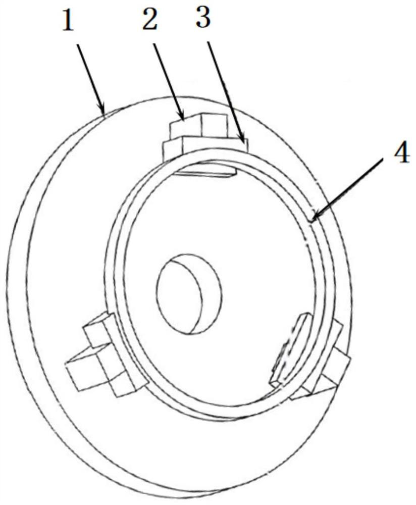
[0036] S1 rough turning first sequence: use the chuck to support the original end ring 4 blanks, use chuck 1 to support the inner hole for preliminary rough turning processing, rough turn the end face, rough turn the outer circle, and the unilateral allowance is 0.75mm, and get the rough turn first sequence rear end ring;

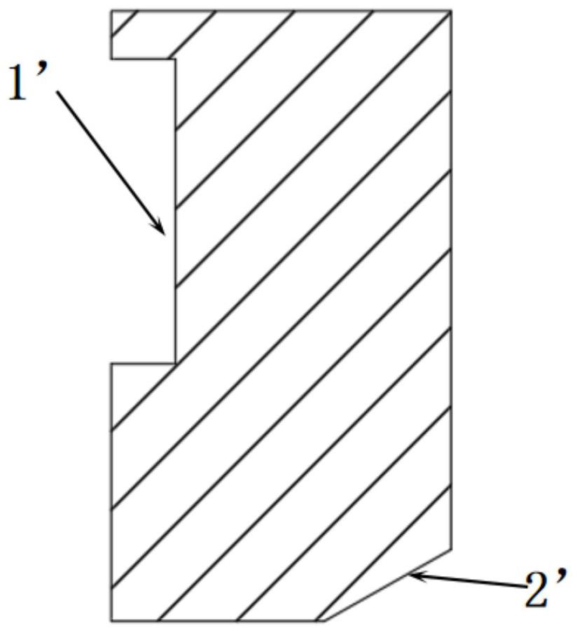
[0037] S2 rough turning second sequence: face adjustment, use chuck 1 to clamp the outer circle of the rear end ring of rough turning, rough turning end face, rough turning inner hole, unilateral allowance is 0.70mm; then start the end face groove 1', groove The inner diameter, outer diameter and the unilateral margin of the groove bottom are 0.55mm, and the thick second-order rear end ring is obtained;

[0038] S3 finish turning first step: face adjustment, use chuck 1 to support the inner hole of the rear end ring of the second step, finish turning the end face and outer ...

Embodiment 2

[0042] A process for turning a chrome-zirconium copper end ring, comprising the following process steps:

[0043] S1 rough turning first sequence: use the chuck to support the original end ring 4 blanks, use the chuck 1 support inner hole to perform preliminary rough turning processing, rough turn the end face, rough turn the outer circle, and the unilateral allowance is 0.65mm, and get the rough turn first sequence rear end ring;

[0044] S2 rough turning second sequence: face adjustment, use chuck 1 to clamp the outer circle of the rear end ring of rough turning, rough turning end face, rough turning inner hole, unilateral allowance is 0.70mm; then start the end face groove 1', groove The inner diameter, outer diameter and the unilateral margin of the groove bottom are 0.60mm, and the thick second-order rear end ring is obtained;

[0045] S3 finish turning first step: face adjustment, use chuck 1 to support the inner hole of the rear end ring of the second step, finish turn...


PUM

PropertyMeasurementUnit
surface smoothnessaaaaaaaaaa

Abstract

The invention relates to an end ring turning process. The end ring turning process comprises the process steps of S1, primary rough turning, S2, secondary rough turning, S3, primary finish turning and S4, secondary finish turning. According to the end ring turning technology, the turning technology of rough turning and finish turning is adopted, the machining allowance is adjusted, the allowance of rough turning machining is reduced, the machining amount of finish machining is reduced, the cutting stress and the cutting temperature are reduced, and machining deformation is reduced; the finish turning amount is reduced, copper cuttings are easy to break, and meanwhile the copper cuttings are prevented from scratching the surface of a workpiece; during finish turning, tool marks are avoided; the working procedures are adjusted, and the coaxiality and the inner hole size precision are improved; clamping jaws of the chuck are wide jaws with large contact surfaces, so that the end ring is not easy to deform; the processing precision, the smooth finish, the surface brightness, the product processing quality stability and the like of the product are improved, and the problem of tool marks is thoroughly avoided due to the processing of the end surface groove; the processing efficiency is improved and the cost is reduced.

Description

technical field [0001] The invention belongs to the technical field of generator rotor end ring processing, and in particular relates to an end ring turning process. Background technique [0002] The motor is composed of two parts, the rotor and the stator. It is a device used to realize the conversion of electrical energy and mechanical energy and mechanical energy and electrical energy. The motor rotor is the rotating part of the motor. transfer transfer in . The groove of the end ring is mainly the guide bar soldered to the outer circle of the motor core. It connects the two ends of all the guide bars and plays the role of conducting current. If there is a problem, it will affect the power generation of the whole machine and endanger the normal run. With the development of current technology and equipment, the requirements for machining accuracy, smoothness, and surface brightness of the end ring are getting higher and higher. Can not meet the current technical require...

Claims


Application Information

Patent Timeline
Patent Type & Authority Applications(China)
IPC IPC(8): B23B1/00
CPCB23B1/00
Inventor 王新李海峰王勇杰
Owner YANTAI WANLONG VACUUM METALLURGY
Why Eureka
Try Eureka